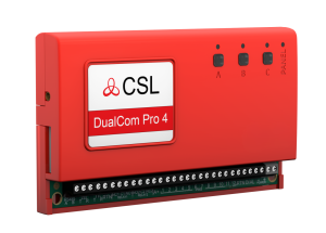
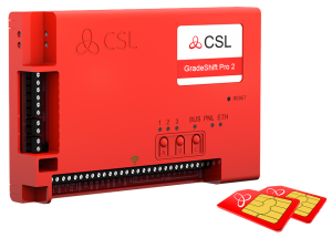
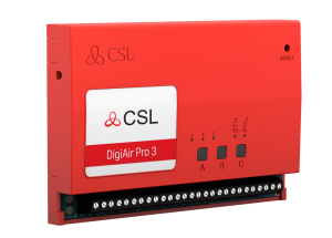
DualCom Pro 2 Range - Fire Quick Guide

Guide

This document covers the requirements of a Fire installation and is a supplement for the DualCom Pro 2. New information includes:

RESISTOR VALUES REQUIRED PER INPUT (10K, 4K7)

MOUNTING

This device should be mounted inside the Fire Alarm Panel or inside a separate powered housing, using the sticky mounting pads supplied. Enclosure requirements for the DualCom Pro 2 Fire are the same as for the Fire Alarm Panel itself. The enclosure must provide the facility to indicate the state of the fault and acknowledge outputs on the device. For Fire Alarm Panels, the enclosure must meet the requirements of EN54-21 7.3 (e.g. IP30 or above) and the supplied sticker should be applied to the outside of the housing.

INPUTS

Input 1: used for receiving the Fire Alarm/Restore signal from the CIE.

Input 2: used for receiving Fault/Restore signal from the CIE.

Inputs 3, 5, 6, 7, 8, 9 10, 11 & 12: used for receiving PIN inputs from any other device (i.e. security CIE). These PINs take a lower priority than 1 & 2 when signalling.

Input 4: used to indicate if the site is open/closed.

The alarm codes generated by these inputs are as follows

SIA

Pin 1: UA8001/UR8001

Pin 2: UA8002/UR8002

ALARMS

Pins 1 and 2 are dedicated for use with fire panels and will respond to different conditions, these are:

• Alarm and restore

• Open circuit and open circuit restore (tamper)

• Short circuit and short circuit restore (tamper)

The type of alarm message that is sent will depend on what happens across the PIN(s). Below are the different conditions and messages the Dualcom Pro 2 Fire will generate:

When 10k is seen on PINs 1 & 2 it will show a non-alarm state, when this changes to 14k7 it will go into an alarm state. If the circuit is broken it will generate an open circuit tamper alarm. If it sees 0v closed circuit, it will generate a short circuit tamper alarm.

PINs 1 & 2 come as normally open going closed, out of the box. If you require the input to be set as 14k7 in non-alarm and 10k in alarm, follow the inverting process below.

INVERTING

To invert, when the PIN is in an alarmed state, hold the C button. The wiring configurations are as follows:


FAULT RELAY

1 - The power is removed.

2 - There is a short circuit in any of the interconnections between the CIE and the device.

3 - There is an open circuit in any of the interconnections between the CIE and the device.

4 - An acknowledgement has not been received from the Gemini Global Platform within the allotted time after a Fire Alarm has been sent (within 100 seconds for Type 1).

5 - There are no transmission paths available. Please note, all available paths must fail before a fault warning is given.

A FIRE ALARM WILL NOT RESTORE UNTIL ALL FAULTS (ON THE WIRING OR PANEL) ARE CLEARED

FAULT RELAY SHOULD BE WIRED TO THE FIRE PANEL FAULT INPUT OR TO A SEPARATE LIGHT EMITTING INDICATOR AS REQUIRED BY EN54-21 5.3.B

FAULT OUTPUT

On the DualCom Pro 2 Fire, outputs NO1, C1 and NC1 are volt-free, normally closed going open when the following conditions are seen:

• Open circuit across either PIN 1 & PIN 2 (tamper)

• Short circuit across either PIN 1 & PIN 2 (tamper)

• ATS failure (both paths when available)

• Power is lost on the unit

Wiring configurations (depending on what is required at the fire panel) see below.


FAULT RELAY WIRING

The first option is to wire into the fire panel’s fault PIN. The example on the next page shows a 0v common, a 12-30v can also be used to carry across the DualCom Pro 2’s relay. In Fire Mode, relay 1 is INVERTED, so the relay is closed between NO1 and C, it will open under fault conditions. This cannot be changed. If the panel has a fault relay, it can also be wired as a closed circuit going open in fault:

ACKNOWLEDGEMENT OUTPUT

DualCom Pro 2 Fire Relay 3 (not used) Relay 2 (ACK)Relay 1 (Fault) NO3C3NC3NO2C2NC2 C1NC1A+PIN 1PIN 2 Relay 2 is a normally open going closed. It will activate when an alarm/fire/fault remove signal (PIN 1 & PIN 2) is generated and will pulse closed for 5 seconds. Below is the wiring configuration. The acknowledgement relay should be used to indicate the successful receipt of a Gemini Global Platform acknowledgement (within 100 seconds) either at the Fire Alarm Panel or by a separate light emitting indicator, as required by EN54-21 5.3.a.

For specifications please see the main DualCom Pro 2 Quick Guide. When the ARC acknowledges an alarm signal, the DualCom Pro 2’s relay 2 will pulse closed for 5 seconds. The wiring for this is as follows: