
Step 1 - Site Survey
Step 2 - Installation
Step 3 - Test & Self Learn
Step 4 - Check Signals
Step 5 - Advanced Instructions
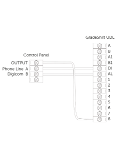
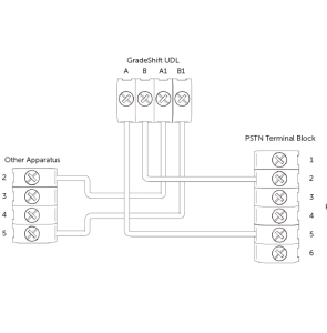
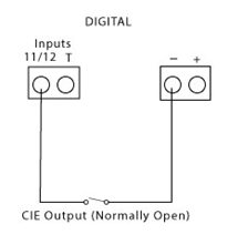
Step 6 - Wiring
Troubleshooting
Fire Guide
Technical Specifications
| Dimensions | 21 mm (h), 132mm (w), 94mm (d) | ||||||||||||
| Weight | 140g including NVM and SIM | ||||||||||||
| Temperature | -20C to +60C transit, -10C to +50C operating | ||||||||||||
| Humidity | 0 – 80% non-condensing | ||||||||||||
| Mounting | Any orientation | ||||||||||||
| Warranty | 5 years | ||||||||||||
| Power Requirement | 9.0v – 30.0v | ||||||||||||
| Current Consumption | Quiescent = 20 mA Signalling = 200 mA |
||||||||||||
| LED Indications |
|
||||||||||||
| Radio Path | 2G GSM and 3G GPRS services | ||||||||||||
| Aerial | 50 ohm (nominal) on MMCX socket | ||||||||||||
| Operation Method | Store and Forward (SIA) Pass Through (Fast Format/CID) | ||||||||||||
| CIE Interconnections | Input ‘pin triggering’ (Parallel) 12 channels, Analogue (Dial Capture), RS232 Serial, RS485 Bus |
||||||||||||
| RCT Protocols | Fast Format/Contact ID/SIA | ||||||||||||
| Input Terminals | Max +30v, Min 0 Vdc (reference supply 0v terminal) 100k pull-up resistor to +5v |
||||||||||||
| Low Battery | 9.8v falling, 12.0v recovery | ||||||||||||
| Fault Output | Changeover contacts (60v max, 100mA max) | ||||||||||||
| Aux Output | Normally Open contact, may be inverted (60v max, 100mA max) |
||||||||||||
| General Purpose outputs | Four. Each switched to 0v (30v max, 100mA) | ||||||||||||
| User Serviceable Parts | There are no user serviceable parts within the GradeShift | ||||||||||||
| Standards | Suitable for use in alarm systems complying to: EN50136-1:1998 Security Grade 4/DP3 EN50136-2:2012 SP3 (RADIO) SSF 114 v2 Larmklass 2 EN50131-10 Type Y ATS Classification: EN50136 ATS5/SP3 ATS 5 parameters: D3/M3/T4/S2/I3/A3 |
||||||||||||
| Environmental | EN50136/EN50131 Environmental class II Device should not come into contact with water |
||||||||||||
| Emissions | EN55022 | ||||||||||||
| Installation | The CS5301-01 shall be installed by a service person and be powered by a Limited Power Source in accordance with clause 2.5 of EN 60950-1 or equivalent, not exceeding the maximum voltage of 30 Vdc, capable of delivering a minimum current of 200mA and be current limited (fused) to 1A. It shall be installed inside an enclosure of another I&HAS component which shall be that of a CIE conforming to EN 50131-3, or a PSU conforming to EN 50131-6. |
Figure 2 – LED Indications
| LED LABEL | DESCRIPTION | LED STATUS | |||
| ON | FLASHING | OFF | OTHER | ||
| Green | GPRS Signal Strength | Strong Signal Strength | Acceptable Signal Strength | Low Signal Strength, not acceptable | LED off and Red Fault LED on indicates no signal |
| Yellow | Communications | Input is triggered or Dial Capture is in progress | Sending a message to Gemini and ARC | No communication is in progress | Rapidly flashes to show successful communication |
| Red | Fault | Fault present see troubleshooting section | NVM contains factory defaults | No faults exist | On for 2 seconds indicates communication failure |
| Blue | Ready | Unit is ready to send messages to Gemini and ARC | N/A | Unit is busy and not ready to send new messages | LED off and Red Fault LED on indicates programming file is yet to be downloaded (usually takes 5-8 mins from power up with good signal) |
| Service (SVC) (next to aerial socket) | Network Status | N/A | SIM card registered on network | There is insufficient power or no power connected to the DualCom | Rapid flashing indicates unit is not registered to network |
Why is a Broadband Filter necessary?
What if there appears to be random triggering of the DualCom?
What if the Telephone path signal is not received by the Alarm Receiving Centre?
What if the Radio path signal has not been received by the Alarm Receiving Centre?
What if the Wired LAN (IP) signal has not been received by the Alarm Receiving Centre?
Is the GradeShift UDL dual-path capable?
Which path is the primary signalling path?
How can I tell if all the signalling paths are working?
How does the GradeShift UDL interface with my panel?
Does the LAN path support DHCP?
Can the LAN path be changed to Static IP?
Does the GradeShift UDL need ports opened to work on LAN?
What are the Destination IP addresses for the LAN path?
What is the best way to test path fails to the ARC?
What polarity do I need to use to trigger the pins on the GradeShift UDL?
Customer IT Survey Form
The Customer IT Survey Form may be required when ordering LAN + Radio or LAN-only devices.
The DualCom Pro will require an IP address to be allocated to it by the customer’s network administrator.