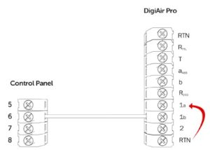
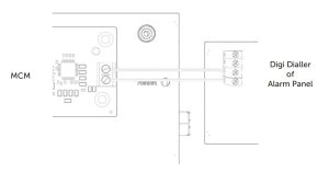
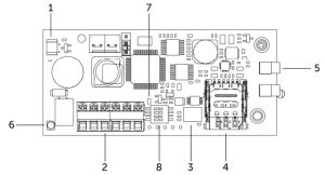
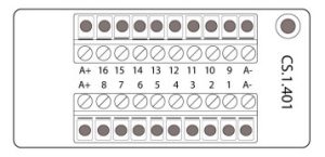
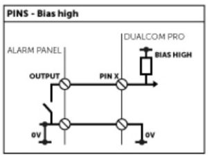
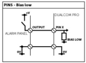
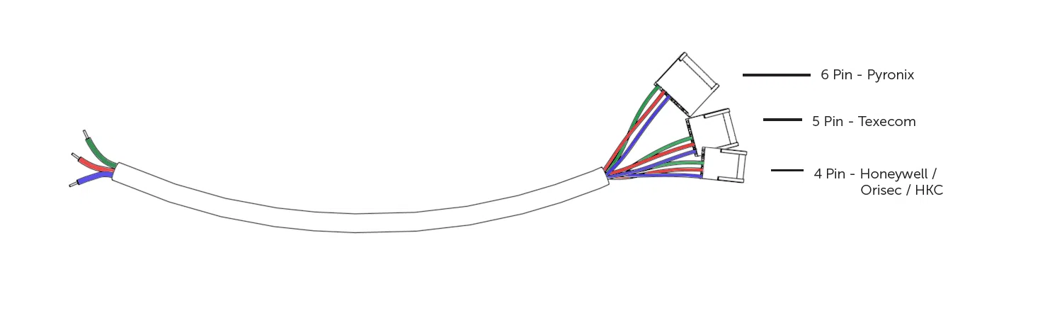
Refer to step 3 in the main quick guide for information on pins and serial connections
GradeShift Pro
GradeShift Pro Radio/Radio uses two active 4G WorldSIMs, each with their own radio module, one as the primary and one as the secondary path. A third standby SIM acts as a backup to the primary SIM on the primary path. GradeShift Pro LAN/Radio uses LAN connectivity for its primary path and a 4G WorldSIM as its secondary path. A standby WorldSIM is also supplied. Each SIM operates on an independent network from the other for total resilience.


Quick Guide
Introduction
The DualCom Pro Range offers Installers easier, faster installation of a professional signalling system with even greater resilience, plus access to CSL Live, our brand new ordering and management portal.
Using the onboard serial connections or pin triggering, DualCom Pro is compatible with a wide range of control equipment including systems installed to EN50136 & PD6662. The range consists of DigiAir Pro – our single path solution that utilises a Radio path to signal an alarm; and GradeShift Pro – our dual path solution that utilises a combination of two Radio paths or one Radio and one LAN path to signal an alarm.
It’s as Easy as 1, 2, 3
Most DualCom Pro units are ready to go after these few simple steps


Whilst your DualCom Pro 2 downloads its configuration

For customisation use the CSL My Base App/Web Portal. For panel configuration instructions see our online guides
Need a My Base Account?
Need One Time My Base Access?
Need Panel Configuration Instructions?
Step 1 - Site Survey
Variants with Radio
Use a Signal Analyser (available from the CSL Installer Shop) to determine if enough base stations (2 or more) are available at the site and that they can supply sufficient signal strength (30% and above). This will determine the optimum location for the DualCom’s aerial to be mounted.
If you do not have a Signal Analyser we recommend powering up the DualCom Pro, connecting the aerial/s, going through the commissioning process and checking the signal strength before permanently fitting the aerial. We recommend signal strength on the DualCom Pro should be 3 (30%) or above.
Variants with LAN
Ensure there is a LAN port adjacent to the alarm panel. DualCom Pro uses DHCP as default, fixed IP settings can be added/amended in My Base through the CSL Live App/Web Portal or via the A & B buttons. Fit the Ethernet Cable to the device (as per Figure 2) and connect to the customer’s router. Ensure the customer’s LAN socket is live and has the correct network setting, as per below:
• Port 50561 open for outbound traffic
• NAT enabled
• UDP data
The LED on the LAN connector adaptor will flash green to indicate connection.
Step 2 - Installation
DualCom Pro must be installed within an enclosure suitable for the installation certification. The unit should be fixed securely using the adhesive pads supplied or via the screw fixings accessible by removing the lid.
Once fitted, ensure:
- As required the aerial/aerials are connected and/or the LAN connector is installed
- The alarm panel or PSU is powered down, then connect the DualCom Pro PWR +ve and –ve terminals to the 12/24V DC output of the control equipment
- If required, connect the serial cable – RS485, RS232 or TTL (panel dependent) – see Figure 1 for more information
- Connect any hardwired alarms into the device – see Figure 4
- Connect the fault output
- Restore power to the alarm panel or PSU
IN ORDER TO MAINTAIN COMPLIANCE WITH THE REQUIREMENTS FOR ELECTRICAL SAFETY THE DUALCOM PRO SHOULD BE POWERED FROM A FUSED CONNECTION WITH FOLLOWING RATING:
• FOR A 12V DC SYSTEM (SUPPLY VOLTAGE IN THE RANGE 10VDC TO 14VDC) A FUSE RATED AT 1.25
• FOR A 24V DC SYSTEM (SUPPLY VOLTAGE IN THE RANGE 20VDC TO 36VDC) A FUSE RATED AT 600 MA
IF THE POWER SOURCE IS NOT LIMITED TO THESE VALUES, THEN A FUSE WITH THE CORRECT RATING MUST BE FITTED IN LINE WITH THE POSITIVE CONNECTION FROM THE POWER SOURCE
Do |
|
Don’t |
|
Step 3 - Commissioning
On power-up, the DualCom Pro will automatically contact the Gemini Global Platform to perform its commissioning process, which will take up to 5-8 minutes. During this time the display will show ‘N’ to indicate it is a new device, followed by ‘C’ as commissioning is in progress and ‘R’ to indicate it is fully commissioned and ready for use.
During this process you may see ‘SIM NOT READY’ displayed. This is normal and will clear once completed.
LEDs
Figure 3 – LEDs ON INITIAL POWER UP
LED 1 – POWER | LED 2 – COMMUNICATION PATH | LED 3 – COMMISIONING |
![]() No light = The DualCom Pro does not have power | ![]() No Light = No paths working yet or the DualCom Pro does not have power | ![]() No Light = No communication path found |
![]() Green Solid Light = The DualCom Pro is powered and is running valid firmware | ![]() Amber Solid Light = One communication path is working | ![]() Amber Flashing Light = Communication path found |
![]() Green Solid Light = Two communication paths are working | ![]() Green Flashing Light = Commissioning Server found, contacting the Alarm Server | |
![]() Green Solid Light = Fully commissioned |
CHECKING SIGNAL STRENGTH
Signal strengths can be easily checked via the My Base App for each path. To view the signal strength on DualCom Pro, wait for the device to commission. The display will read out the RAT (Radio Access Technology) and the signal strength of the primary Radio Path (i.e. GSM1 4G 8). If you have a secondary radio module, toggle DIP switch 4 to show the RAT and signal strength of GSM 2 (ie GSM2 4G 6).
SIGNAL STRENGTH IS SHOWN AS A READING OUT OF 10
PIN TRIGGERING
For this operation the device is triggered by removing or applying zero volts to input terminals 1-8. No external pull-up resistors will be required. This is generally achieved via the digital communicator outputs of a control panel. The unit will signal alarm conditions and will generate the relevant messages and forward them via the Gemini Global Platform to the ARC. Installers are advised that the intended use should avoid situations where the rate of trigger exceeds the rate at which messages are received at the ARC receiver.
Figure 4 – Example of pin triggering wiring

PIN INPUT CONFIGURATION
If you need to change the input from negative removed to negative applied, this can be done on CSL Live via My Base. If you need to use positive applied/removed you will need to change the pin profile on My Base and manually change the bias on the device using the Self Learn feature:
• Ensure all required pins are in a restore/quiescent state and you are out of the device menu
• Press and hold the C button until L appears on the display
• Release the C button
• The display will confirm successful operation by displaying ‘LEARN OK’
OUTPUTS
Output default is normally open. Output 1A + 1B are volt free contacts, that are normally open and configured to indicate path fail conditions to the control panel.
IF THE DEVICE IS POWERED BY 24V (FIRE PANEL), + TERMINAL SHOWN WILL STILL DELIVER 12V.
Output 2 is a single wire switch negative output with a 100mA max current. As default, this output is unused but is configurable by calling CSL Technical Support.
Figure 5 – Example of Fault Output Wiring


DIAL CAPTURE
DualCom Pro can be fitted with an optional Modem Capture Module (purchased separately – part number CS.1.402). When using this module, it must be plugged into the main board via the connector shown on
Figure 1.
If you are using a dual radio variant of the DualCom Pro, the plug-on radio module must be removed and refitted into the Tamper Proof Case and connected via the RS422 BUS connections on both boards. With the radio module removed the Modem Capture Module can be fitted onto the DualCom Pro. Both the Modem Capture Module and Tamper Proof Case (part number CS.1.500) can be purchased via the CSL Installer Shop. Please follow the instructions provided within the product.
PANEL CONNECTION
Your device will come pre-configured without a panel connection (pins only). To enable serial connection to a control panel, go to My Base and select the panel type.
Alternatively, contact CSL Technical Support via support@csl-group.com or call +44 (0)1895 4744 44.
SERIAL / RS232 / 485 / TTL PANEL CONNECTIONS
As standard, the DualCom Pro range is supplied with a serial cable compatible with Honeywell (RS485), Orisec (TTL), Pyronix (RS232) and Texecom (TTL) panels. Other types may require an additional cable/plug in purchased on our Installer Shop – see Figure 7 for more information.
Figure 6 – Panel Connection Information
MANUFACTURER | PANEL | CONNECTION | CABLE/PLUG ON | SUPPLIED CABLES |
Honeywell | Galaxy | RS485 | 4 Pin (cable provided) | Green – RTN Blue – RS485-B Red – RS485-A |
Orisec | All | TTL | 4 Pin (cable provided) | Green – RTN Blue – TTL-T Red – TTL-R |
Pyronix | Euro | RS232 | 6 Pin (cable provided) | Green – RTN Blue – RS232-R Red – RS232-T |
Texecom | Premier/Elite | TTL | 5 Pin (cable provided) | Green – RTN Blue – TTL-R Red – TTL-T |
For Risco, Eaton and UTC, please purchase the relevant cable from the CSL Installer shop. For other connections or further instructions on Control Panel programming please review the Panel Guides on the Installer Zone of our website: www.csl-group.com/uk/installer-zone-panel-guides
Figure 7 – Serial Cable (RS232/485/TTL)

Step 4 - Testing
Please also ensure that you put your device on test with the ARC and perform a full range of test signals from your control equipment. DualCom Pro paths can be tested using the following method:
• Tap button A until S is shown
• Tap button C to indicate Path Test
• The display will read out PATH TEST and return to Menu S for 30 seconds before returning to signal strength
Once you have successfully tested your device, make sure that you check with your ARC to see that they are receiving signals. This can be achieved by calling your ARC or using their web based secure platform.
IF THE DEVICE IS POWERED BY A 24V (FIRE PANEL), THE + TERMINAL SHOWN WILL STILL DELIVER 12V
MY BASE APP
My Base provides Installers with the ability to manage and configure DualCom Pro 2 devices on a handy App/Web portal.
Simply download CSL My Base from your appropriate App store and obtain log-in information from CSL (or the CSL web administrator within your company) to access these great features:
- View path status
- Check signal strength
- View panel connection status
- Configure static IP information
- Change pin configuration
- Check ATS path availability
- Remotely upgrade device firmware
- View Alarms
- Test Alarm
- Invert Fault Relay
- Configure Outputs
- Amend Smart Reports
- Add Estate name
APPENDIX
Figure 8 – Selected Button Configuration Descriptions
MENU | MESSAGE | DESCRIPTION | CONFIGURABLE | ADDITIONAL |
1 | IP-Addr = | Device’s local (LAN) IP address | Yes | Can also be set in My Base |
5 | Router = | Default gateway | Yes | |
6 | NetMask = | Local network subnet mask | Yes | |
B | Pins = | Status of each pin | No | R = Restore A = Alarm |
L | Pin-Bias = | Reads and sets the inputs bias | Yes | H – High State L – Low State |
M | Alt-Disp = | Change display to show alternative transmission path statuses | Yes | |
N | Pri-Fail = | Fails the primary transmission path | N/A | Y = Force path fail |
O | Sec-Fail = | Fails the secondary transmission path | N/A | Y = Force path fail |
P | Pri-Status = | Reads out status of primary interface | N/A | |
Q | Sec-Status = | Reads out status of secondary interface | N/A | |
R | Panel-Status = | Reads out status of panel interface | N/A | |
S | Paths-Test = | Sends signals over all paths for testing | N/A |
Figure 9 – Button Configuration
TAP | HOLD | |||
A BUTTON | ||||
Scrolls up through menu options | N/A | |||
B BUTTON | ||||
Scrolls down through menu options | N/A | |||
C BUTTON | ||||
Read Menu Option | Edit selected menu programming settings. When the button is held an ‘_’ (underscore) will appear. You can then scroll through the available options |

Figure 10 – LEDs DURING NORMAL OPERATION
LED 1 | LED 2 | LED 3 | LED 4 | LED 5 |
![]() Red Solid Light = | ![]() Red Solid Light = | ![]() Red Flashing Light | ![]() No Light = | ![]() No Light = |
![]() Green Flashing Light = Poor But Usable Signal | ![]() Green Flashing Light = Poor But Usable Signal | ![]() Amber Flashing Light = Not commissioned | ![]() Red Solid Light = | ![]() Red Solid Light = |
![]() Green Solid Light = Good Signal | ![]() Green Solid Light = Good Signal | ![]() Green Flashing Light = | ![]() Green Solid Light = Transmitting data | ![]() Green Solid Light = Transmitting data |
![]() Green Light Solid = Commissioned with no errors |
RADIO TROUBLESHOOTING
How can I fail my signalling paths without having to disconnect them?
To fail each path select menu options N or O
• Menu N – Fails primary path
• Menu O – Fails secondary path
Using the A or B button scroll until you see menu N or O on the display, then press and hold the C button until you see (_). Press the A or B buttons to toggle between Y & N, then press C to select the option.
Y = Yes, fail the path.
N = Normal, restore the failed path.
“Y” will only fail the path for a total of 15 minutes.
What does the flashing dot in the right-hand side of the display indicate?
The flashing dot in the right-hand corner of the display indicates that DualCom Pro is actively transmitting data.
How can I check the signal strength of each radio module?
You can check the signal strength of each radio module on a commisioned device via the My Base App. Alternatively you can toggle between the signal strength of each radio module, move DIP Switch 4 of the secondary radio module to ON or OFF (opposite position). The display of the DualCom Pro will read GSM 1 or GSM 2 followed by the Radio Access Technology (RAT) and signal strength between 1-10 (10-100%) dependant on the radio module.
Does my unit have a roaming SIM?
Yes, all variants of DualCom Pro devices come with at least 2 Roaming 4G SIMs
If the signal strength of my DualCom Pro is under 3 (30%) what can I do to improve my signal strength?
For all radio variants:
• Avoid coiling the aerial cable
• Move the aerial away from electrical equipment/wiring
• Move the aerial to a higher point in the property or closer to a window/door
Where you are using a dual radio variant, it is possible to purchase an additional Radio/Wi-Fi Module Enclosure with in-built aerials. This will enable you to locate the secondary radio module in a different location. Please visit the CSL Installer Shop for more information.
Fire Guide
This document covers the requirements of a Fire installation and is a supplement for the DualCom. New information includes:
Resistor values required per input (10K, 4K7) |
Mounting
This device should be mounted inside the Fire Alarm Panel or inside a separate powered housing, using the sticky mounting pads supplied. Enclosure requirements for the DualCom Pro Fire are the same as for the Fire Alarm Panel
itself. The enclosure must provide the facility to indicate the state of the fault and acknowledge outputs on the device. For Fire Alarm Panels, the enclosure must meet the requirements of EN54-21 7.3 (e.g. IP30 or above) and the supplied sticker should be applied to the outside of the housing.
Inputs
- Input 1: used for receiving the Fire Alarm/Restore signal from the CIE.
- Input 2: used for receiving Fault/Restore signal from the CIE.
- Inputs 3, 5, 6, 7 & 8: used for receiving PIN inputs from any other device (i.e. security CIE). These PINs take a lower priority than 1 & 2 when signalling.
- Input 4: used to indicate if the site is open/closed.
The alarm codes generated by these inputs are as follows:
SIA
Pin 1: UA8001/UR8001
Pin 2: UA8002/UR8002
Alarms
Pins 1 and 2 are dedicated for use with fire panels and will respond to different
conditions, these are:
- Alarm and restore
- Open circuit and open circuit restore (tamper)
- Short circuit and short circuit restore (tamper)
The type of alarm message that is sent will depend on what happens across the PIN(s). Below are the different conditions and messages the Dualcom Fire Pro will generate:
When 14k7 is seen on PIN 1 & PIN 2 it will show a non-alarm state, when this changes to 10k it will go into an alarm state. If the circuit is broken it will generate an open circuit tamper alarm. If it sees an 0v closed circuit, it will generate a short circuit tamper alarm.
PINs 1 & 2 come as normally open going closed out of the box. If you require the input to be set as 10K in non-alarm and 14K7 in alarm, follow the inverting process below.
Inverting
To invert, when the PIN is in an alarmed state, hold the C button until L is displayed.
This should be done outside of the menus.
The wiring configurations are as follows:
Fault Reporting
To meet the EN54-21 requirements for monitoring on Type 1 and Type 2 Fire systems, this device sends regular polling calls to the Gemini Global Platform on all connected and active transmission paths. The Installer shall ensure that a reporting action has been agreed with the ARC for all alarm codes, transmission path failure notifications and polling failure reports from the Gemini Global Platform.
Fault Relay
- The power is removed.
- There is a short circuit in any of the interconnections between the CIE and the device.
- There is an open circuit in any of the interconnections between the CIE and the device.
- An acknowledgement has not been received from the Gemini Global Platform within the allotted time after a Fire Alarm has been sent (within 100 seconds for Type 1).
- There are no transmission paths available. Please note, that all available paths must fail before a fault warning is given.
A Fire Alarm will not be restored until all faults (on the wiring or panel) are cleared Fault Relay should be wired to the Fire Panel Fault Input or to a separate light emitting indicator as required by EN54-21 5.3.b
Fault Output
On the DualCom Pro Fire, outputs 1a and 1b are volt-free, normally closed going
open when the following conditions are seen:
- Open circuit across either PIN 1 & PIN 2 (tamper).
- Short circuit across either PIN 1 & PIN 2 (tamper).
- ATS failure (both paths when available).
- Power is lost in the unit.
Wiring configurations (depending on what is required at the fire panel) see below:
Acknowledgement Output
Output 2 (ACK) is an open-collector driver that pulls low when activated. It will activate when an alarm/fire/fault restore signal (PIN 1 & PIN 2) is generated and will pulse low for 5 seconds. Below is the wiring configuration (resistor value dependent on what is required at the fire panel):
After 100 seconds (for Type 1) has expired, as mentioned previously. The acknowledgement relay should be used to indicate the successful receipt of a Gemini Global Platform acknowledgement either at the Fire Alarm Panel or by a separate light emitting indicator, as required by EN54-21 5.3.a
![]() | CSL DualCom Ltd., Salamander Quay West, Park Lane, Harefield, United Kingdom, UB9 6NZ | www.csl-group.com |
DoP No. 2544-CPR-P21114-F01-17 | Notified Body No. 2544 | |
EN 54-21:2006 Fire detection and fire alarm systems / Alarm transmission and fault warning routing equipment EN 50131-10:2014, EN 50136-1:2012, EN 50136-2:2013 | Type of transmission system: Type 1 DP4 Security Grade: 1-4 depending on the I&HAS housing in which it is installed. Environmental Class: II |
Technical Specs
Technical Specs
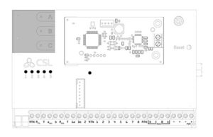
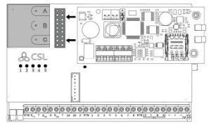
ENSURE AERIAL / AERIALS ARE INSERTED INTO THE MMCX CONNECTOR WITH THE RED DOT.
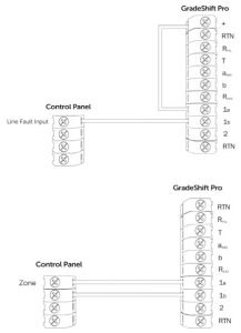
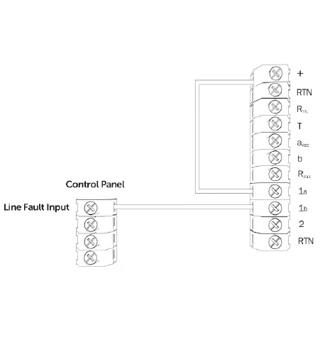
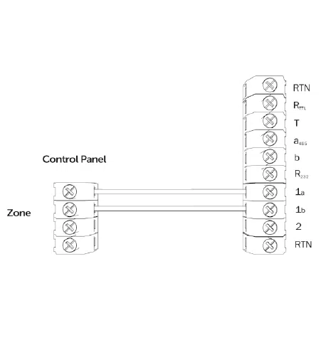
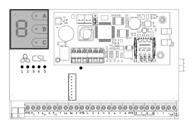
Figure 1 – Diagram

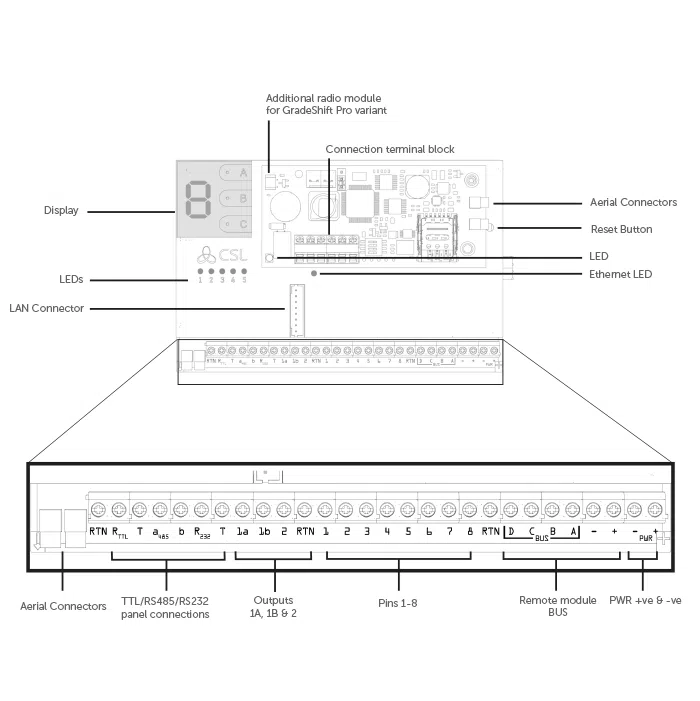
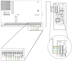
Figure 2 – LAN Adaptor

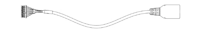
To enable the device to use LAN, you will need to connect the LAN adaptor (above) to the LAN Connector (on the DualCom Pro).
Dimensions | 75 mm (h) x 119mm (w) x 15mm (d) or 75mm (h) x 119mm (w) x 32mm (d) with secondary radio module |
Weight | 113g excluding aerial |
Temperature | -10 °C to + 55 °C |
Humidity | 0 – 90% non-condensing |
Mounting | Via fixing points under main cover |
Warranty | Please refer to our terms and conditions. |
Power Requirement | 10 – 36 Volts DC In order to maintain compliance with requirements for electrical safety the Dualcom Pro should always be powered from a fused supply with following rating:
If the power source is not limited to these values, then a fuse with the correct rating must be fitted in line with the positive connection from the power source. |
Current Consumption | DigiAir Pro = 35mA (Avg. Value) GradeShift Pro – LAN/Radio = 40mA (Avg. Value) GradeShift Pro – Radio/Radio = 175mA (Avg. Value) |
Radio Path | 2G, 3G, 4G |
Aerial | 50 ohm (nominal) on MMCX socket |
Operation Method | Store and forward |
Input Terminals | Max +30v, Min 0 volts DC (reference supply 0v supply) 100k Low Battery 7.6V DC +/- 0.5 VDC |
RCT Protocols | SIA |
User Serviceable Parts | There are no serviceable parts within the DualCom Pro Range |
Environmental | Class II |
Applicable Standards | Suitable for use in alarm systems complying to: EN50131-1:2006+A2:2017 EN50131-10:2014 Type Y EN50136-1:2012+A1:2018 SP1,SP2,SP3,SP4,DP1,DP2,DP3,DP4 EN50130-5 Emissions Standard – 2014/53/EU (RED) PD6662:2017 / PD6669:2017 ATS Classification: EN50136 ATS5/DP4 Max ATS 5 parameters: D3/M3/T4/S2/I3/A3 |
DigiAir Pro
PATH | AVAILABLE GRADES | WHAT’S IN THE BOX | PART NUMBER |
Radio | SP2 | DigiAir Pro 2, serial cable & small aerial | CS.51.R2 |
LAN | SP2 | DigiAir Pro, serial cable, Ethernet Cable & LAN connector adaptor | CS.51.L2 |
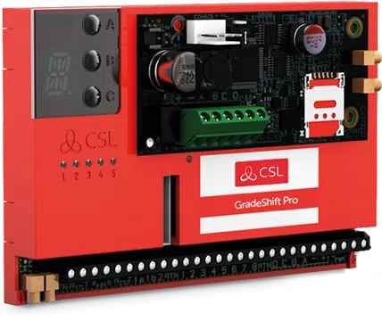
GradeShift Pro
PATH | AVAILABLE GRADES | WHAT’S IN THE BOX | PART NUMBER |
LAN + Radio | DP2 DP2+ DP3 DP4 | GradeShift Pro, serial cable, single T-bar aerial, Ethernet Cable, & LAN connector adaptor | CS.53.LR2 CS.53.LR2P CS.53.LR3 |
Radio + Radio | DP2 DP2+ DP3 | GradeShift Pro, secondary radio module, serial cable, Dual T-bar aerial | CS.53.RR2 CS.53.RR2P CS.53.RR3 CS.53.RR4 |

Panel Guides
FAQS
What is the My Base App?
The My Base app is a self-service management platform for the newest generation of CSL devices. For DualCom Pro & DualCom Pro 2 devices. You can check your signal strength, request regrades, send test alarms, view availability graphs, edit panel profiles, upgrade firmware and view alarm logs.
How do I gain access to the My Base App?
Once you’ve installed My Base from your applicable App Store, please register for access.
For security, we’ll contact you in order to authorize your request and set the appropriate permission levels for your My Base account. Once approved, we’ll send you your login credentials.
Need Support? Call CSL Technical Support on +44 (0) 1895 474 444.
How do I setup Multi-Factor Authentication on the My Base App?
For security, multi-factor authentication (MFA) is now required to use the My Base App. MFA drastically increases security on our platform and requires users to authenticate themselves via their username/password and with a time-limited code (each code expires after 60 seconds). This code is obtained via an Authenticator App, email or SMS. New authentication is required once every 30 days; if the user logs out or if we update CSL Live.
How it works:
- Log in to My Base as normal with your username and password.
- Receive a code via an Authenticator App, email or SMS.
- Enter the code within My Base.
- You are now securely logged in.

If you have any issues with the steps above, resetting your password will restart the authentication process. If the issue persists and you require support, call CSL Technical Support on +44 (0) 1895 474 444.
Which Authenticator Apps work with My Base?
Here is a list of commonly used authenticators approved by CSL:
- Google Authenticator
- Microsoft Authenticator
- LastPass Authenticator
- 2FA Authenticator (2FAS)
- Aegis Authenticator
- Authy
- Due Mobile
- IBM Security Verify
- Free OTP
My login credentials aren't working on My Base, what shall I do?
Resetting your password will restart the multi-factor authentication process and resolve most issues with logging on. If you’re not receiving an email or text with your one-time access code you’ll need to call CSL Technical Support to update your contact details, please call +44 (0) 1895 474 444
How do I edit the LAN configuration of a GradeShift Pro Device?
Please watch our short explainer video on this subject – Click here
How do I check all paths are connected?
Please watch our short explainer video on this subject – Click here
Can I use the onboard serial connection as well as pin triggering at the same time with the Gradeshift Pro?
Yes, you can.
What is the standard pin setup of the Gradeshift Pro?
As standard, the device is triggered by removing or applying zero volts to input terminals 1-8. No external pull-up resistors will be required. This is usually achieved via the digital communicator outputs of a control panel.
If you need to use a positive applied/removed, please contact support so that they can amend the bias of the device.
How do I carry out the pins self-learn feature on the Gradeshift Pro?
Please watch our short explainer video on this subject (Click here) or follow the below instructions.
1. Ensure all required pins are in a restore/quiescent state and you are out of the device menu
2. Press and hold the C button until “L” appears on the display
3. Release the C button
3. The display will confirm successful operation by displaying ‘LEARN OK”
4. All pins will now be in a restore state, please test with the ARC
Why are pin alarms not coming through on the alarm log?
As standard the device is triggered by removing or applying zero volts to input terminals 1-8. If you are using a positive applied/removed to trigger the pins, you will not see any pin alarms in the alarm log until the bias of the device has been changed. You can amend this by carrying out the following steps:
1. Using the A or B button, scroll until you see an “L” on the display.
2. Hold and press the C button until you see an “ _ “ on the display.
3. Using the A or B button, scroll until you see an “L” on the display.
4. Tap the C button.
5. The bias has now been changed.
Alternatively, please contact technical support for assistance.
Why am I not receiving SIA signals from my panel?
Your device will come pre-configured without a panel connection type (pins only). To enable the serial connection to a control panel, go to MyBase and select the panel type.
1. To so this, follow the below steps:
2. Go to hardware. Click on the “hamburger” icon and select “edit panel”.

3. Select the correct panel type in panel 1 and then click on “save changes”.

4. Your device will upload its configuration and reboot. Once the reboot has taken place you should start receiving signals from the control panel.
If you are not receiving signals, make sure you have completed the panel programming steps detailed in the panel guide for that particular control panel. The guides can be found on online – Click here
How do I check the signal strength of my device (both primary and secondary path)?
To check the signal strength the device is registering you can use either My Base or the display of the device. The display will read out the radio access technology and the signal strength of the primary radio path (i.e GSM 1 4G 8). We recommend a minimum of 4 out of 10 on 4G/3G/2G.
If you have a secondary radio module, toggle DIP switch 4 of the module to show the signal strength and radio access technology of GSM2 on the display (i.e GSM2 4G 6). Toggle DIP switch 4 again to view signal for GSM 1.
Do I need to use both aerial connectors on the device?
No, only ANT 1 is used in the UK.
Is it possible to invert the polarity of just one pin?
No, all pins either must be negative applied/removed or positive applied/removed. There cannot be a mixture of negative and positive.
Why is the display of my device showing a continuous H or T?
If your device has been configured as single path IP, you will see one of the below network configurations displayed on the device’s display:
“T” = 10-Base T connection – half duplex.
“T” with “.” = 10-Base T connection – full duplex.
“H” = 100-Base T connection -half duplex.
“H” with “.” = 100-Base T connection -full duplex.
What does “Missing 4G Pod 2” alarm mean?
You will see this alarm in the alarm log, if radio module 2 has been installed in one of our radio module enclosures and the device has detected an issue with the optical tamper of that enclosure. Ideally, an engineer should attend site and ensure the enclosure has not been tampered with.
What is the standard setup of the GradeShift Pro's fault output?
The output default is normally open. Outputs 1A + 1B are volt free contacts, that are normally open and configured to indicate path fail conditions to the control panel. If required, you can invert the relay output via My Base.
Useful Links
Customer IT Survey Form
The Customer IT Survey Form may be required when ordering LAN + Radio or LAN only devices.
The DualCom Pro will require an IP address to be allocated to it by the customer’s network administrator.
CSL Remote Manager
More information about the CSL Remote Manager is available here.
Line Faults
GradeShift Pro: Dual Path Line Fault
Misc profile required: Line fault DP DO (Line fault dual path, dual output)
(It is up to the engineer to choose which zone in the panel the line fault terminals will be wired into.)
Loop between RTN and 1A.
DigiAir Pro: Single Path Line Fault
Misc profile required: Line fault SP SO (Line fault single path, single output)
(It is up to the engineer to choose which zone in the panel the line fault terminals will be wired into.)
Loop between RTN and 1A.
Modem Capture Module
Product Description
Product Code: CS.1.402
The Modem Capture Module (MCM) is designed to integrate between the DualCom Pro and an Intruder Alarm Panel’s Digital Communicator (Digi). The MCM emulates a telephone line (PSTN) for Digi connectivity between the panel and the DualCom Pro. The MCM is an accessory that has been designed to couple up with the DualCom Pro.
Installation
- Power down the DualCom Pro.
- Place the MCM onto the available Aux Header on the DualCom Pro.
- Double-check the DualCom Pro pins are aligned to the MCM’s socket.
- Apply gentle pressure to push the MCM onto the DualCom Pro.
- Please use the supplied M2.5 x 6mm screw to secure the MCM onto the DualCom Pro.
- Connect Line Terminals A & B to the Alarm Panel’s Digital Communicator Terminals (Digi).
- Re-apply power to the DualCom Pro.
- Go to www.csl-group.com/installer for the panel integration instructions.
Please note: you must ensure the device is powered down before fitting the MCM.
MCM Panel Monitoring
The DualCom Pro and MCM are normally installed in the Alarm Panel (Control Panel). Therefore, the chances of the interconnect being compromised maliciously are low. An output from the Control Panel is configured to change when the Control Panel detects a problem with the MCM interface – this is known as Line Fault.
The Control Panel Line Fault Output is connected to an input on the DualCom Pro.
Input 2 should be used when wiring.
The DualCom Pro is configured to signal an equipment fault when the output changes state.
The polarity of the output and the sense of the input need to be selected to match the capabilities of the panel but should be set so that a break in the wiring results in a fault being reported.
The DualCom Pro uses one of its outputs to signal the status of the Alarm Transmission System (ATS) to the alarm panel.
RM8 Relay Module
Product Description
Product Code: CS.1.235
The RM8 Relay Module is compatible with any control panel that has a plug-on DualCom footprint (panel size dependent).
Relay Module PCB Layout
Installation
Before attempting to install the Relay Module, isolate ALL power from the control panel. Do not continue if there is power still present on the control panel as this could damage the Relay Module, control panel or both.
- Ensure that the Relay Module is the correct way up (see diagram on the reverse side of this guide)
- Press down on the Relay Module until it is fitted correctly
- Reconnect power to the control panel
Connecting Output
The Relay Module has 8 outputs. These outputs can be used to drive auxiliary devices. Each output is a clean contact (relay rates at 3A & 12V). The diagram below shows typical wiring examples for the outputs:
Pin Triggering
Step 1 – Put the DualCom Pro on test with the ARC
Step 2 – Mount the DualCom Pro in the panel and connect the aerial provided
Step 3 – Wire panel digi outputs to the DualCom Pro’s inputs and connect the FLT relay to the panel (see figure 1). There are 2 options, wire to a zone or utilise panel’s FLT input (panel dependant)
Step 4 – Apply 12-24v power
Step 5 – Wait 5 minutes whilst your DualCom Pro downloads its configuration
Step 6 – Check LED status. LEDs 1 & 2 should have solid green or flashing lights, whilst LED 3 should have a solid green light. If showing otherwise please contact CSL Technical Support on +44 (0) 1895 474 444
Step 7 – Self learn
- Ensure all required pins are in a normal/quiescent state and the panel is in its day state
- Press and hold the C button until L appears on the display, then release the C button
- The display will confirm the successful operation by displaying ‘LEARN OK’
Step 8 – Test available paths to the ARC
- Tap button A until S is shown
- Tap button C to indicate the Path Test
- The display will read out PATH TEST
Step 9 – Test all channels to the ARC, and confirm test calls and inputs have all been received
correctly
Figure 1 – Fault output 1a & 1b
4G Radio Module
Product Description
The DualCom Pro 4G Radio Module allows you to upgrade an existing/new DualCom Pro installation with an additional 4G signalling path. This Module can be remotely located inside the building using the supplied Radio Module Enclosure by connecting to the RS422 Data Bus (max cable distance 50m). Locating the Radio Module away from the DualCom Pro enables the installation to benefit from better radio signals in other parts of the building and increases the security of your system.
When using an additional plug on board (i.e. 16 Pin input card or Module Capture Module) you must install the second Radio Module in the Radio Module Enclosure. Where not using an additional plug on board you can plug the Radio Module directly onto the DualCom Pro using the AUX port.
Figure 1 – Diagram
1 – Lid Tamper (Plastic-box mounted) | 5 – External Aerial Connectors |
2 – RS422 Data-Bus connections | 6 – Tri-Colour LED |
3 – MIM | 7 – Bi-Colour LED |
4 – SIM Carrier | 8 – DIP switches |
LED
Figure 2 – LED Status
Tri-Colour – Large LED
Colour | Mode | Meaning |
Blue | Solid | No / Bad SIM |
Red | Slow Flash | SIM not registered |
Red | Solid | SIM Connected (Not commissioned to infrastructure) |
Yellow | Solid | Connected, Commissioned – Communications LOST Comms |
Green | Solid | Connected, Commissioned – Communications GOOD Comms |
White | Fast Flash | Never seen a working path – BAD Comms |
Bi-Colour – Small LED
Colour | Mode | Meaning |
Red | Slow Flash | No usable signal |
Red | Solid | Poor signal (Signal unreliable) |
Amber | Solid | Normal signal |
Green | Solid | Good signal |
Red / Green | Alternating Blinking | Lost communication with the device |
Red | Fast Flash | Power problems |
Installation
Option 1
Using the 4G Radio/WiFi Module Enclosure
- Ensure the DualCom Pro and alarm system are powered down before connecting the device
- Screw the module into the plastic enclosure using the break-off plastic hole.
- Connect the cable as per the wiring diagram (Figure 3) using a CAT-5 Cable and wire the aerial
- Power up the alarm system and the DualCom Pro
- Check the LED on the bottom left-hand side of the radio module is green
Figure 3 – Wiring when using the 4G Radio/LAN Module Enclosure
Option 2
Connecting the DualCom Pro 4G Radio Module directly to the device
- Ensure the DualCom Pro and alarm system are powered down before connecting the device
- Connect the 4G Radio Module to the AUX port, making sure that it is correctly aligned. Connect the aerial (see Figure 1) and fit the supplied retaining screw to hold the board in place (see Figure 3)
- Power up the alarm system and the DualCom Pro
- Check the LED on the bottom left-hand side of the radio module is green
Figure 4 – Connection when connecting the DualCom Pro 4G Radio Module directly onto the device
DIP Switches
The 4G Radio Module has a block of DIP-switches located under the Data-Bus Terminals. The table below describes their functionality.
DIP Switch | Function | Configuration |
DIP 1 | RS422/485 EOL | Switch to ON if running on remote RS422 Bus |
DIP 2 | RS422 EOL | Switch to ON if running on remote RS422 Bus |
DIP 3 | RS485 Mode | Always leave as OFF. |
DIP 4 | Radio Module Signal Strength | Switch to OFF to show radio module 1 signal strength Switch to ON to show radio module 2 signal strength |
Cable Length
Where the 4G Radio Module is taking its power from the DualCom Pro, a maximum cable run of 50 meters must not be exceeded. If additional cable length is required, a local power source is required to supply the 4G Radio Module with power.
Technical Specifications | |
Supply Voltage | 13.5v |
Current Consumption | 35mA (average) 200 mA (max) |
Dimension (PCB only) | (L) 85mm x (W) 35mm x (H) 20mm |
Weight (Unpackaged) | 110g |
Power Supplies
If you require a Power Supply Unit (PSU) for your MiniAir installation, our partners, Elmdene, provide a suitable solution.
Visit their website for more information about the Li-Power PSU.
16 Input Expander Card for DualCom Pro
Product Description
The 16-input Expander Card is designed to expand the quantity of signalling inputs available on the DualCom Pro. This Expander Card can provide up to an additional 16 pins and is used to send alarm signals in a SIA format to an Alarm Receiving Centre (ARC).
Installation
Using the 16 Input Expander Card
1. Ensure the DualCom Pro and alarm system are powered down.
2. Place the Expander Card onto the AUX Header on the DualCom Pro.
3. Double-check the DualCom Pro pins are aligned to the Expander Card’s socket.
4. Apply gentle pressure to place the Expander Card onto the device.
5. Use the supplied M2.5 x 6mm screw to secure the Expander Card onto the DualCom Pro.
6. Carry out any necessary wiring between the panel and Expander Card (see page 2).
7. Power up the alarm system and the DualCom Pro.
Please note: alarms sent from the 16 Input Expander Card will be sent as an untyped alarm and will
be displayed with a 10 prefix e.g. expander card channel 7 = 107.
Hardware Inputs
If your DualCom Pro is powered by 24V (Fire) the A+ and RTN, terminals will deliver a steady 12V.
Positive/Negative Applied/Remove
Input wiring for positive/negative applied/remove type configurations.
Please note: check the hardwire bias setting.
Figure 1: Pins 1-16, high input threshold, high-low 2.0V DC (max input: 30V DC)
Figure 2: Pins 1-16, low input threshold, low to high 4.0V DC (max input: 30V DC)
Specification
Technical Specification | |
Supply Voltage | 10v – 36v |
Current Consumption | 150 mA (max) |
Dimension (PCB only) | (L) 85mm x (W) 35mm x (H) 20mm |
Weight (unpackaged) | 40g |
Power Consumption
Power Consumption readings for the Pins on the Expander Card on taken as an average.
VOLTAGE | CURRENT (AVERAGE) |
10V | 105mA |
13.8V | 55mA |
36V | 42mA |