
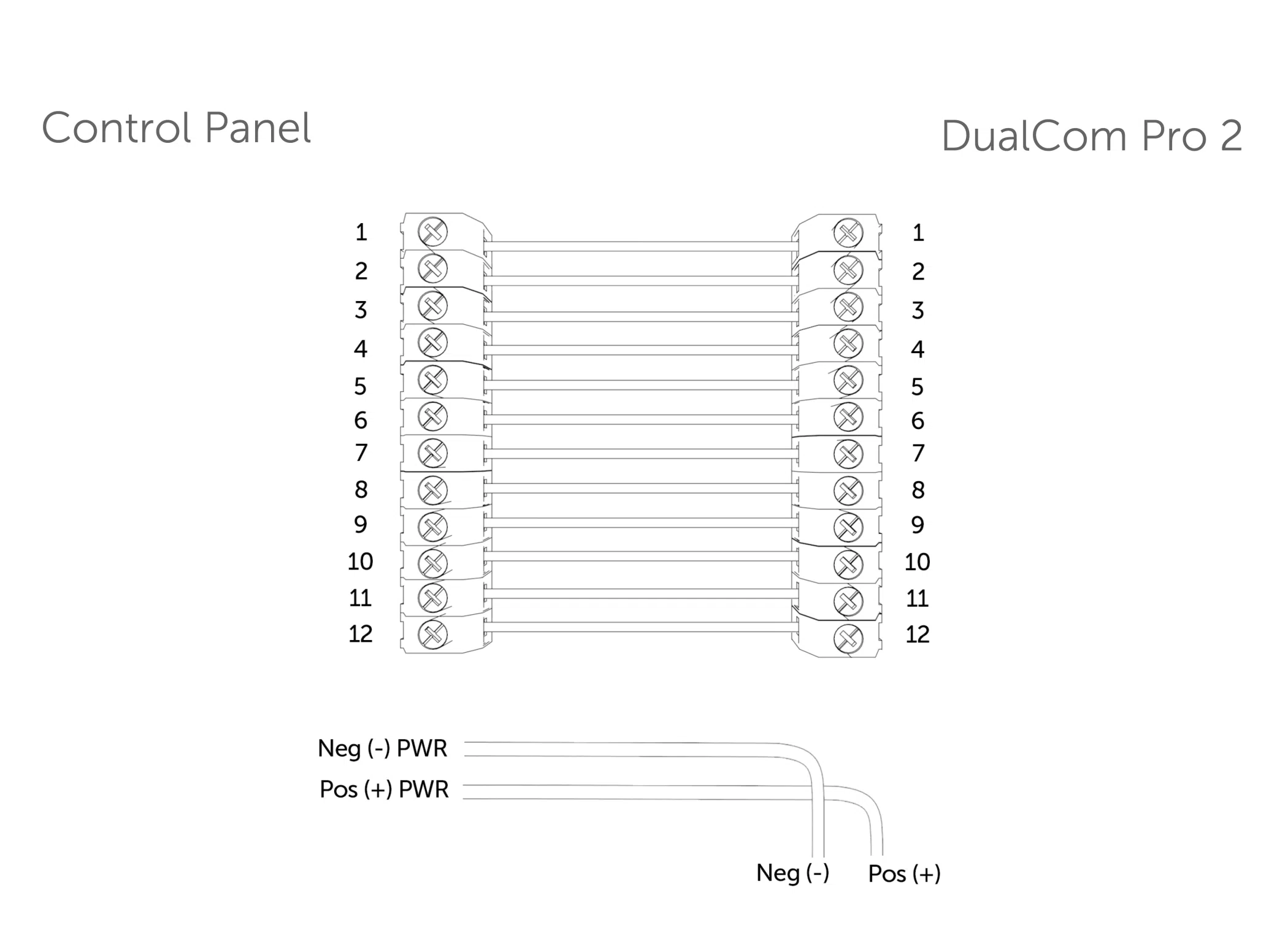
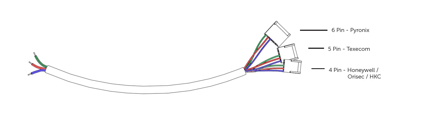
Refer to step 3 in the main quick guide for information on pins and serial connections

Introduction


Step 1 - Site Survey
Step 2 - Installation
Step 3 - Commissioning
Step 4 - Testing
Technical Specs
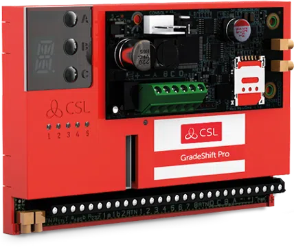
ENSURE AERIAL / AERIALS ARE INSERTED INTO THE MMCX CONNECTOR WITH THE RED DOT.
Figure 1 – Diagram
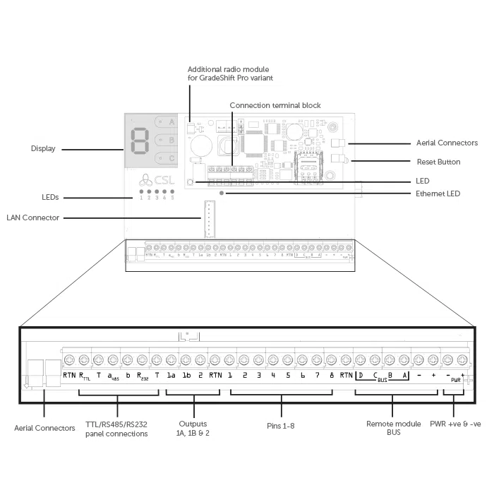
Figure 2 – LAN Adaptor
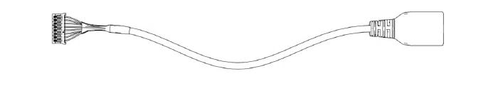
To enable the device to use LAN, you will need to connect the LAN adaptor (above) to the LAN Connector (on the DualCom Pro).
| Dimensions | 75 mm (h) x 119mm (w) x 15mm (d) or 75mm (h) x 119mm (w) x 32mm (d) with secondary radio module |
| Weight | 113g excluding aerial |
| Temperature | -10 °C to + 55 °C |
| Humidity | 0 – 90% non-condensing |
| Mounting | Via fixing points under main cover |
| Warranty | Please refer to our terms and conditions. |
| Power Requirement | 10 – 36 Volts DC
In order to maintain compliance with requirements for electrical safety the Dualcom Pro should always be powered from a fused supply with following rating:
If the power source is not limited to these values, then a fuse with the correct rating must be fitted in line with the positive connection from the power source. |
| Current Consumption | DigiAir Pro = 35mA (Avg. Value) GradeShift Pro – LAN/Radio = 40mA (Avg. Value) GradeShift Pro – Radio/Radio = 175mA (Avg. Value) |
| Radio Path | 2G, 3G, 4G |
| Aerial | 50 ohm (nominal) on MMCX socket |
| Operation Method | Store and forward |
| Input Terminals | Max +30v, Min 0 volts DC (reference supply 0v supply) 100k Low Battery 7.6V DC +/- 0.5 VDC |
| RCT Protocols | SIA |
| User Serviceable Parts | There are no serviceable parts within the DualCom Pro Range |
| Environmental | Class II |
| Applicable Standards | Suitable for use in alarm systems complying to: EN50131-1:2006+A2:2017 EN50131-10:2014 Type Y EN50136-1:2012+A1:2018 SP1,SP2,SP3,SP4,DP1,DP2,DP3,DP4 EN50130-5 Emissions Standard – 2014/53/EU (RED) PD6662:2017 / PD6669:2017 ATS Classification: EN50136 ATS5/DP4 Max ATS 5 parameters: D3/M3/T4/S2/I3/A3 |
DigiAir Pro
| PATH | AVAILABLE GRADES | WHAT’S IN THE BOX | PART NUMBER |
| Radio | SP2 | DigiAir Pro 2, serial cable & small aerial | CS.51.R2 |
| LAN | SP2 | DigiAir Pro, serial cable, Ethernet Cable & LAN connector adaptor | CS.51.L2 |
| Wi-Fi | SP2 | DigiAir Pro, serial cable, Ethernet Cable, Wi-Fi board & Wi-Fi module enclosure |
CS.51.W2 |
GradeShift Pro
| PATH | AVAILABLE GRADES | WHAT’S IN THE BOX | PART NUMBER |
| LAN + Radio | DP2 DP2+ DP3 DP4 |
GradeShift Pro, serial cable, single T-bar aerial, Ethernet Cable, & LAN connector adaptor | CS.53.LR2 CS.53.LR2P CS.53.LR3 |
| Radio + Radio | DP2 DP2+ DP3 |
GradeShift Pro, secondary radio module, serial cable, Dual T-bar aerial | CS.53.RR2 CS.53.RR2P CS.53.RR3 CS.53.RR4 |
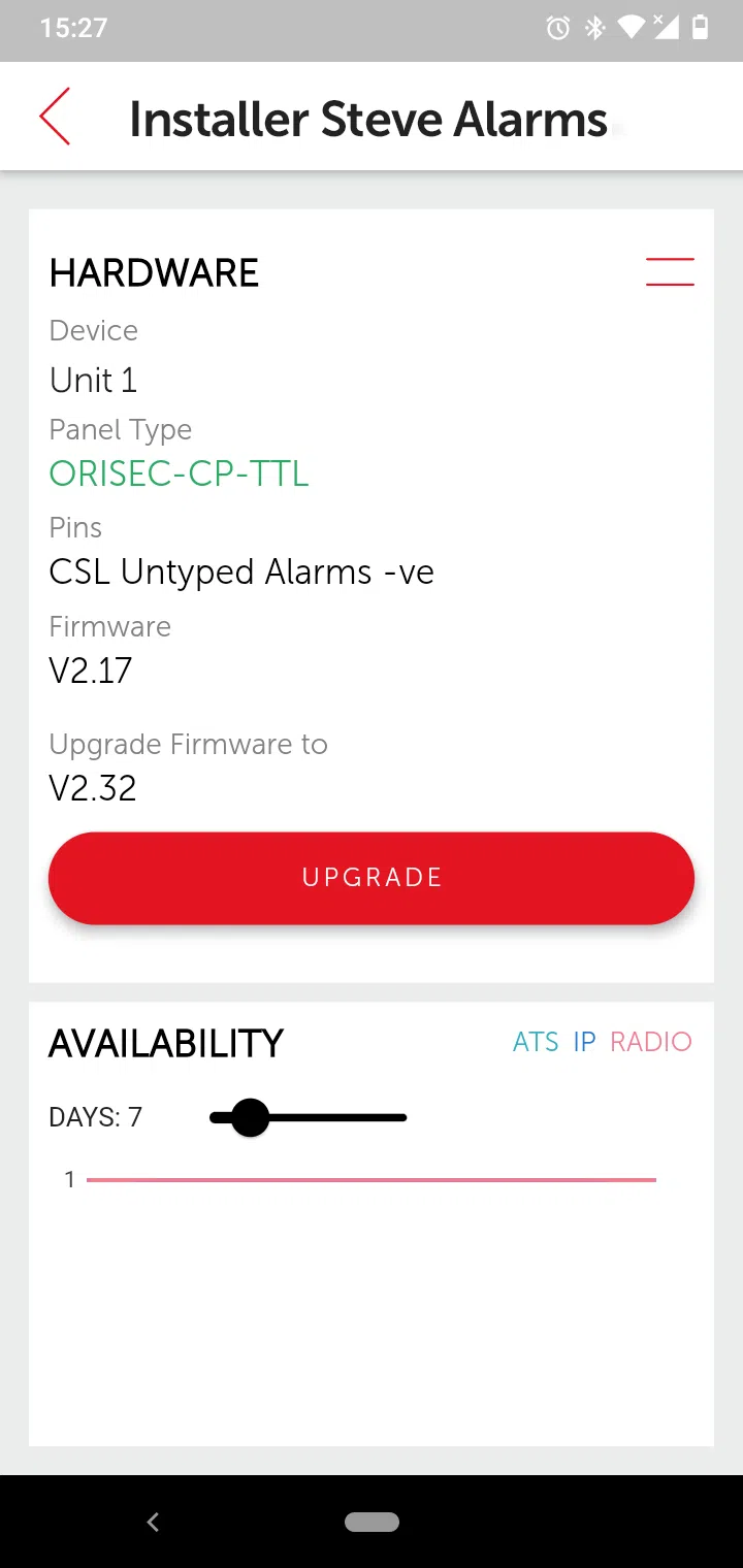
How do I regrade a DualCom Pro device?
What is the My Base App?
How do I gain access to the My Base App?
How do I setup Multi-Factor Authentication on the My Base App?

Which Authenticator Apps work with My Base?
My login credentials aren't working on My Base, what shall I do?
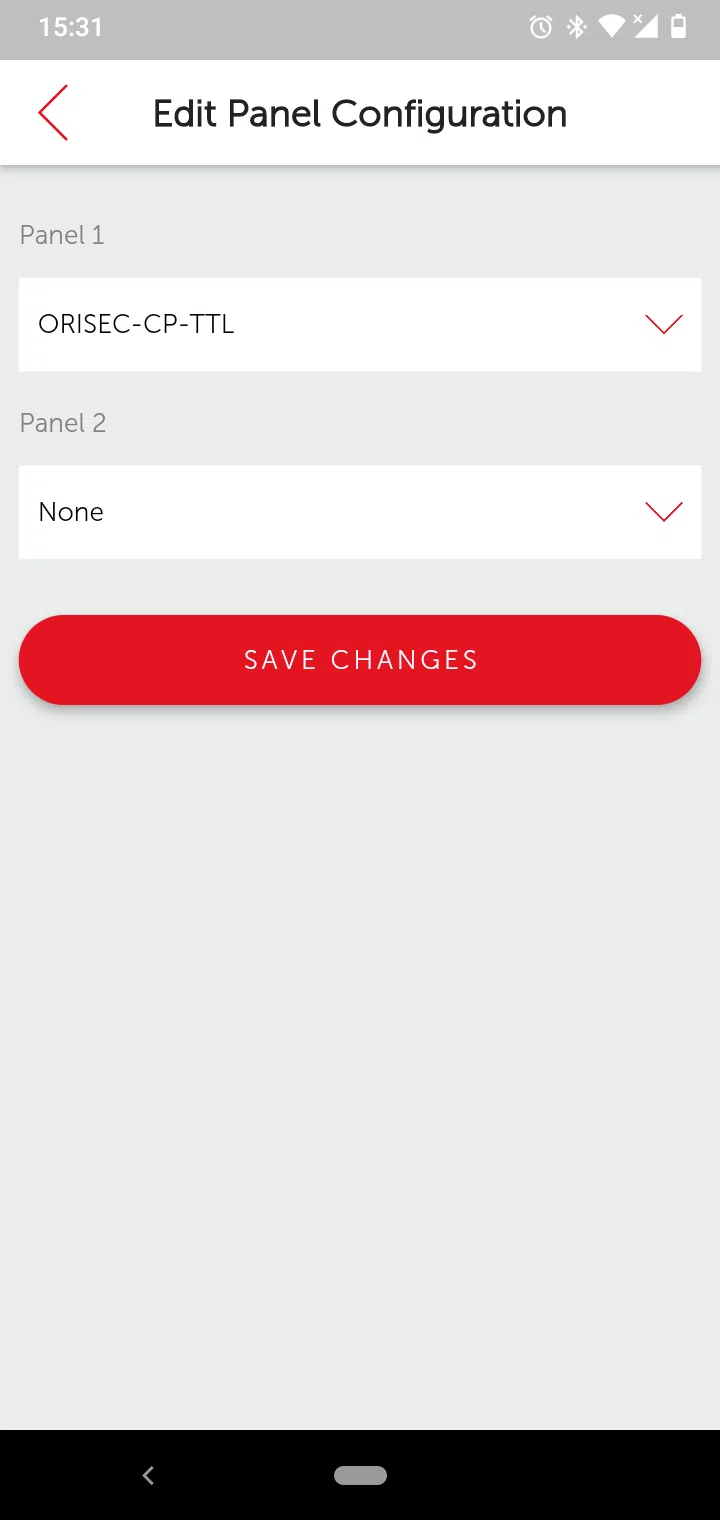
How do I edit the LAN configuration of a GradeShift Pro Device?
How do I check all paths are connected?
Can I use the onboard serial connection as well as pin triggering at the same time with the Gradeshift Pro?
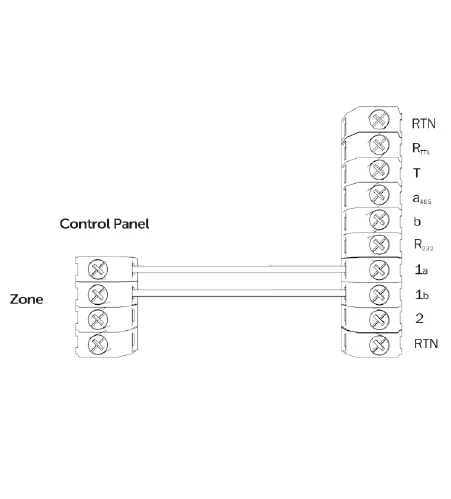
What is the standard pin setup of the Gradeshift Pro?
How do I carry out the pins self-learn feature on the Gradeshift Pro?
Why are pin alarms not coming through on the alarm log?
Why am I not receiving SIA signals from my panel?
How do I check the signal strength of my device (both primary and secondary path)?
Do I need to use both aerial connectors on the device?
Is it possible to invert the polarity of just one pin?
Why is the display of my device showing a continuous H or T?
What does “Missing 4G Pod 2” alarm mean?
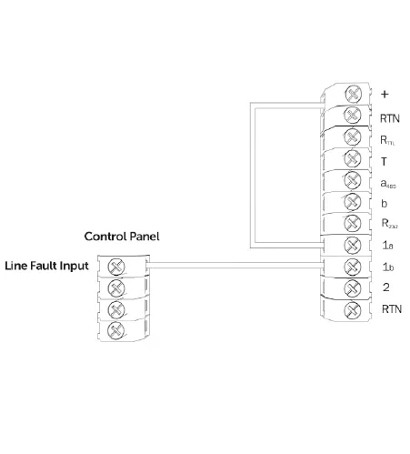
What is the standard setup of the GradeShift Pro's fault output?
Panelguider
För att hitta våra Panel Guider hänvisar vi till vår engelska hemsida.