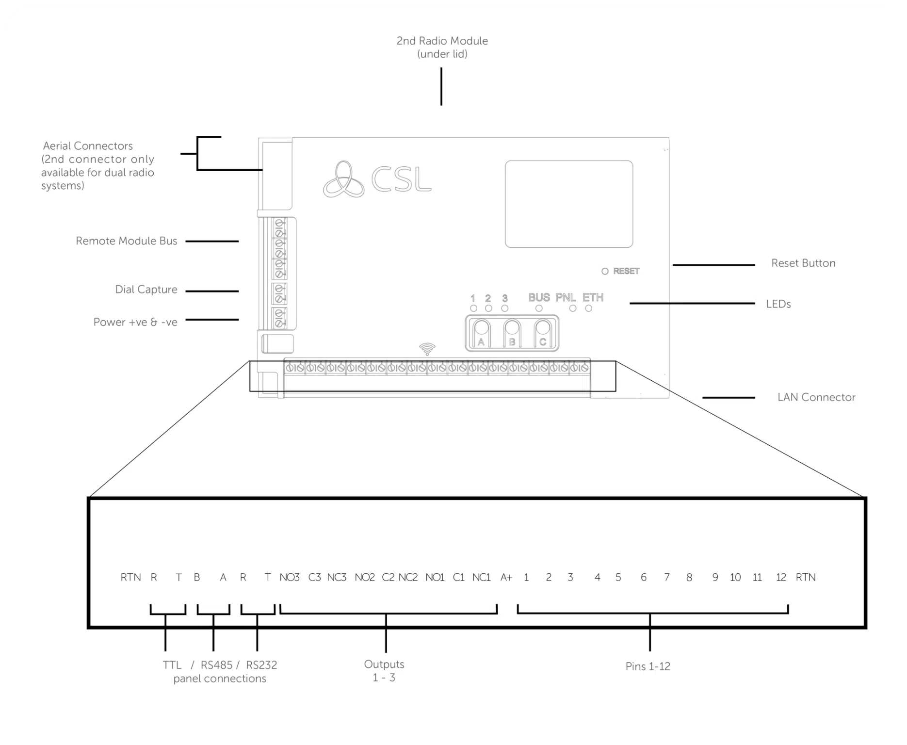

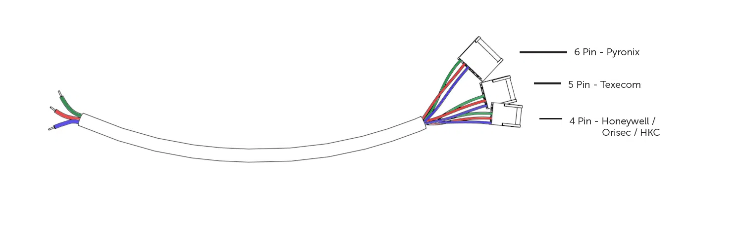
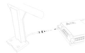
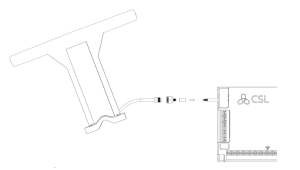
Refer to step 3 in the main quick guide for information on pins and serial connections

Introduction


Step 1 - Site Survey
Step 2 - Installation
Step 3 - Commissioning
Step 4 - Testing
Fire Guide
4G Radio Module Installation Guide

Technical Specifications
| Dimensions | 90mm (h) x 142mm (w) x 22mm (d) |
| Weight | 189g excluding aerial |
| Temperature | -10 °C to + 55 °C |
| Humidity | 0 – 90% non-condensing |
| Mounting | Via fixing points under main cover |
| Warranty | 5 years |
| Power Requirement | 10 – 35 Volts DC
In order to maintain compliance with requirements for electrical safety, the Dualcom Pro should always be powered from a fused supply with the following rating:
If the power source is not limited to these values, then a fuse with the correct rating must be fitted in line with the positive connection from the power source. |
| Current Consumption | GradeShift Pro 2 LAN Radio 12V Power Supply: 100 mA (average value)
GradeShift Pro 2 LAN Radio 24V Power Supply: 63 mA (average value) GradeShift Pro 2 Dual Radio 12V Power Supply: 120 mA (average value) GradeShift Pro 2 Dual Radio 24V Power Supply: 72 mA (average value) |
| Radio Path | 2G, 3G, 4G |
| Output Ratings | Maximum applied voltage = 60VMaximum current = 150mA |
| Aerial | 50 ohms (nominal) on MMCX socket |
| Operation Method | Store and forward |
| CIE Interconnections | Input triggering (standardised parallel), RS232, RS485, TTL |
| RCT Protocols | SIA |
| Input Terminals | Max +30 Volts, Min 0 Volts DC (reference supply 0V) with a + or – 40% change for > 200ms. |
| Low Battery | 7.6V DC +/- 0.5 VDC |
| User Serviceable Parts | There are no serviceable parts within the DualCom Pro Range |
| Applicable Standards | Suitable for use in alarm systems complying to:
Emissions Standard – Radio Equipment Directive 2014/53/EU (RED) EN 50130-5 Environmental Class II ATS Configuration EN 50131-10:2014 Type Y ATS Classification EN 50136-1-1:1998
|
Safety Information:
This equipment is intended for professional installation only.
The DualCom Pro 2 shall be installed within an enclosure or control panel that provides compliance with the applicable system safety standards. The device is designed to be powered from a limited power source (SELV).
Installation and operation shall be carried out in accordance with the instructions provided. Incorrect installation or operation may compromise safety and regulatory compliance.
The product contains radio transmitters. It shall be installed and operated in accordance with the instructions to ensure compliance with applicable electromagnetic field (EMF) exposure limits.
Do not attempt to open, modify, or repair this equipment.
Regulatory Compliance – Radio Equipment Directive (RED)
Hereby, CSL DualCom Ltd declares that the DualCom Pro 2 radio equipment type is in compliance with Directive 2014/53/EU (Radio Equipment Directive).
The product fulfils the essential requirements of the Directive:
- Article 3.1(a): Health and safety
- Article 3.1(b): Electromagnetic compatibility
- Article 3.2: Effective use of the radio spectrum
The full text of the EU Declaration of Conformity is available from the manufacturer (CSL DualCom Ltd) here.
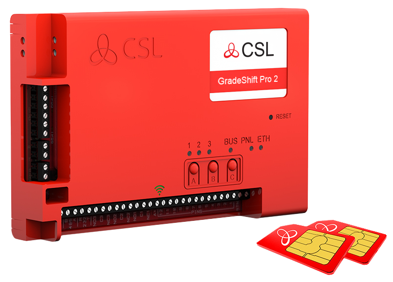
GRADESHIFT PRO 2
| PATH | AVAILABLE GRADES | WHAT’S IN THE BOX | PART NUMBER |
|
LAN + Radio |
DP2 DP2+ DP3 DP4 |
GradeShift Pro 2, serial cable, single T-bar aerial, ethernet cable |
CS.53.LR2 |
|
Radio + Radio |
DP2 DP2+ DP3 |
GradeShift Pro 2, secondary radio module, serial cable, dual T-bar aerial |
CS.53.RR2 |
 |
| 24 |
| CS.51.HWR.02 / CS.51.HWL.02 / CS.53.HW.02 / CS.55.HW.02 / CS.40.104.02 |
| CSL DualCom ltd. Building 4, Croxley Park, Hatters Lane, Watford, WD18 8YF |
| KIWA 0063-CPR-242190024 / 00 |
|
EN 54-21:2006 |
| Type of transmission system: Fire Safety – Type 1 Security – SP2, SP3, SP4, SP5, DP1, DP2, DP3, DP4 Security Grade: 1- 4 depending on the I&HAS housing in which it is installed. Environmental Class: II Certification Body:Kiwa Nederland B.V |
| www.csl-group.com |
What is the My Base App?
How do I gain access to the My Base App?
How do I set up Multi-Factor Authentication on the My Base App?
Which Authenticator Apps work with My Base?
My login credentials aren't working for the My Base App, what shall I do?
How can I fail my signalling paths without having to disconnect them?
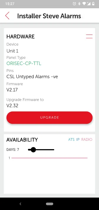
How can I check the signal strength of each radio module?
Does my unit have a roaming SIM?
My signal strength is less than 30% (3/10) or my LED is orange/red. What can I do to improve it?
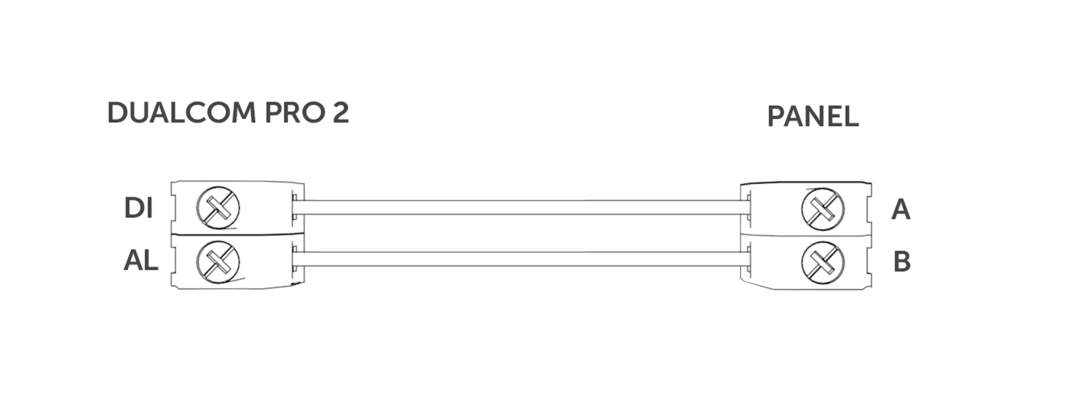
What is the standard pin setup of the GradeShift Pro 2?
Can I use the onboard serial connection as well as pin triggering at the same time with the GradeShift Pro 2?
How do I carry out the pins self-learn feature on the Gradeshift Pro 2?
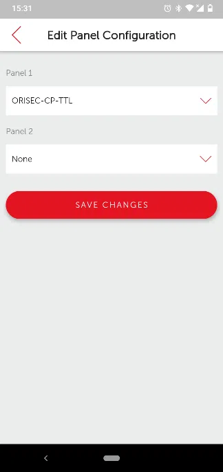
How do I add a panel to my GradeShift Pro 2?
Why are pin alarms not coming through on the alarm log?
Why am I not receiving SIA signals from my panel?
Is it possible to invert the polarity of just one pin?
How can I carry out a path test?
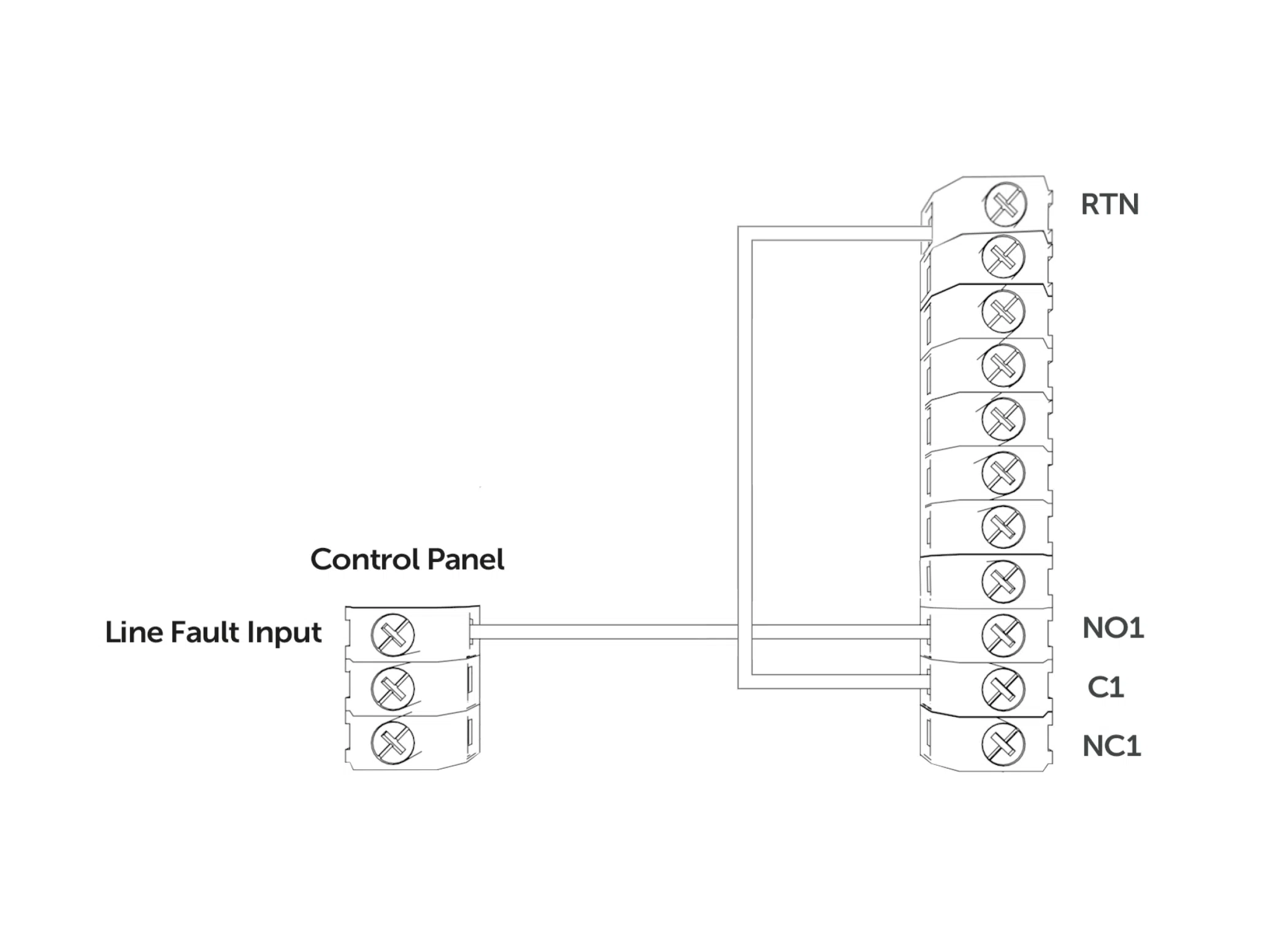
What is the standard setup of the GradeShift Pro 2 fault output?
How do I know if my device has started to commission?
Do I need to use the resistors provided in the box?
Why do the two radio paths of the same device show different signal strength and quality readings?
Customer IT Survey Form
CSL Remote Manager
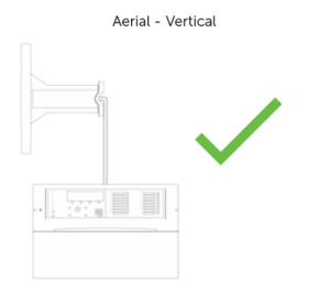
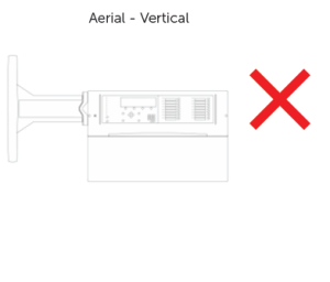
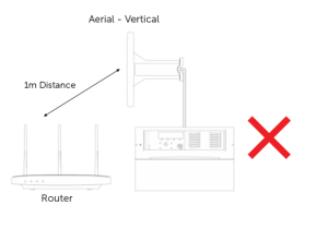
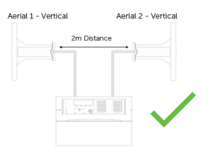
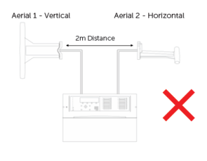
Aerial Fitting Guide
LED Colour Status Guide
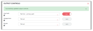
Output Controls

Alarm Signalling Standards
Power Supplies
CSL Live & the My Base App
4G Aerial Upgrade Kit
Technical Notes
Overview
Learn about the latest technical updates and firmware releases.