DigiAir & DigiAir UDL
DualCom DigiAir UDL utilises all mobile networks, via our WorldSIM, to signal an alarm from a protected premise to the Alarm Receiving Centre (ARC). Designed for low to medium risk premises, it is an ideal upgrade for wired digital communicators, as it eliminates call costs and phone charges.


Quick Guide
Introduction
Quick Installation
Installation
- Complete a signal test by ensuring the antenna is connected, applying power and waiting 1-2 minutes for the unit to connect to the network. Once completed, the Green Signal LED should be on or flashing, indicating an acceptable signal. At this time, DigiAir can be located in a suitable enclosure for a grade of installation, and the antenna can be mounted, remembering the Dos and Don’ts outlined at the bottom of this page.
- Connect input triggers, or connect the Dial Capture terminals to a panel’s Digi-Modem PSTN terminals (for further information, please see ‘Installation’ on page 5).
- Connect the fault output terminals to the control panel if required.
- Connect 9-30v DC to the DigiAir.
IF USING A SEPARATE PSU TO POWER THE DIGIAIR, MAKE SURE 0V IS COMMON BETWEEN THE PSU AND THE CONTROL PANEL. |
Registration & Configuration
Test
DO… – INSTALL IN AN OPEN SPACE – COMPLETE A SIGNAL TEST BEFORE INSTALLING INTO FINAL POSITION – FIT VERTICALLY – AVOID SOURCES OF INTERFERENCE I.E. ELECTRICAL INSTALLATION, MONITORS, OTHER WIRELESS EQUIPMENT |
DON’T… – INSTALL WITHIN THE CONTROL EQUIPMENT OR 10CM OF A METAL OBJECT |
Step 1 - Site Survey
Step 2 - Installation
DIGIAIR IS UNABLE TO CONNECT TO THE NETWORK, OR THE SIGNAL IS TOO LOW FOR USE, THE RED FAULT LED WILL LIGHT. DIGIAIR SHOULD ONLY BE USED WITH STRONG OR ACCEPTABLE SIGNAL STRENGTH. IF THE SIGNAL IS LOW, OR THE GREEN SIGNAL LED IS OFF AND THE RED FAULT LED IS ON, TRY TO RE-SITE THE AERIAL – OR USE AN ALTERNATIVE VERSION UNTIL ACCEPTABLE SIGNAL STRENGTH IS ACHIEVED |
CONNECTION USING INPUTS (PIN TRIGGERING)
In this operation, DigiAir is triggered by applying, or removing, zero volts to the input terminals 1-8. No external pull-up resistors will be required. This is generally achieved via the digital communicator outputs of an intruder alarm or similar control panel. DigiAir will signal alarm conditions and will generate the relevant messages, and forward them via Gemini to the ARC. Users are advised that the intended use should avoid situations where the rate of triggering exceeds the rate at which messages may be sent to, or received by, the ARC’s receiver.
IN CERTAIN SITUATIONS THE INPUTS MAY BE TRIGGERED FOR OTHER APPLICATIONS I.E. ENVIRONMENTAL CONTROLS, CCTV, EQUIPMENT MONITORING, ETC. THIS OPERATION IS ACCEPTABLE PROVIDED THE INPUTS ARE TRIGGERED FROM A COMMON POWER SOURCE. |
CONNECTION USING ‘DIAL CAPTURE’
In this operation, DigiAir simulates and replaces the phone line connection to the control panel’s Digi-Modem.
The control panel’s Digi-Modem must use one of the following alarm formats: Fast Format, Contact ID or SIA. In the event the control panel needs to send a signal to the ARC, DigiAir will capture the message and forward it via Gemini to the ARC. The Digi-Modem must have an ARC telephone number and account number programmed for Dial Capture to work. Check your control panel configuration for any other settings that may apply. If you want to monitor the Dial Capture connection, connect an output configured as PSTN line fault on your panel to one of the DigiAir inputs and designate that input as Dial Capture fail at your ARC.
FOR MORE INFORMATION ON COMPATIBLE CONTROL EQUIPMENT PLEASE TO TECHNICAL SPECIFICATIONS. A MIXTURE OF DIAL CAPTURE AND INPUT (PIN) TRIGGERING IS NOT RECOMMENDED WITHOUT CONSULTING CSL TECHNICAL SUPPORT. |
CONNECTION USING RS-485 (DIGIAIR UDL ONLY)
In this operation, DigiAir is triggered by a compatible panel using an RS-485 connection.
The RS-485 connection is capable of accepting alarm information as well as providing Remote Servicing & Diagnostics (RSD) functionality. Figure 5 below shows wiring to a Honeywell panel via input 7 & 8 on the DigiAir, connected to Data A and Data B on the control panel. Once connected,d please contact CSL Technical Support who will assist you in enabling the RS-485 port.
AUX OUTPUT (DIGIAIR UDL ONLY)
DigiAir features a switch negative (0v) auxiliary output which provides up to 100mA when enabled/active. The output can also be inverted. Please contact CSL Technical Support to configure this function, if required.
The aux output can be configured to report:
• Comms successful
• Comms failure
• Radio path fault
• AVI (also requires one or more inputs being selected to AVI)
• Jamming detection
CONNECTING THE OUTPUT (DIGIAIR UDL ONLY)
DigiAir features a volt free changeover output to indicate fault conditions. When installing to PD6662:2017 this output should be wired to the control equipment to indicate path and comms faults.
Power-Up
On first power-up, the 3 DigiAir LEDs will switch on for 3 seconds (not the Yellow Service LED or Blue Ready LED). The unit will establish a connection with, and register on, the radio network. During this time the Yellow Service LED will flash regularly. Once completed, the Yellow Service LED will flash once every 3 seconds and the Green Signal LED will show the radio signal strength if available. See figure 2 on page 3 for LED Indications.
The DigiAir is supplied with ‘factory default’ settings. This is indicated by the Red Fault LED flashing regularly. The first call the DigiAir will make will be to the Gemini Platform, at which point it will automatically download its operational settings, e.g. its chip number – please allow up to 5 minutes for download. This process may also be completed manually (if required) by ensuring the Green Signal LED is on or flashing, then pressing and holding the TEST button for 8 seconds.
PLEASE CONTACT CSL TECHNICAL SUPPORT IF A CHANGE IS REQUIRED TO THE DEFAULT FUNCTION OF THIS OUTPUT. |
LEARNING FOR PIN TRIGGERING APPLICATIONS
For applications using Input ‘pin triggering’, DigiAir needs to identify the normal state of the inputs. To complete this, ensure the control panel is in the normal mode, i.e. no alarm conditions are outstanding. Then press the LEARN button (for 5 seconds) until the Green Signal LED and the Yellow Communications LED flash alternately. A power-up sequence will follow. At any time you may repeat this sequence.
Step 3 - Testing
ALARM TRANSMISSION SYSTEM TESTING
If your DualCom is showing a fault or low signal strength, this must be addressed before leaving the site.
If you are unsure how to test the device, need any explanation of fault messages or general advice please contact CSL Technical Support. Failure to install the device correctly or test regularly will inhibit its operation and delivery of alarm messages.
RESET
The RESET button may be pressed at any time to immediately stop an alarm transmission. This will be followed by a complete power-up sequence. Calls that have not been sent before the reset will be stored and sent when the radio path is re-established. Stored calls may be deleted by pressing and holding the TEST button when RESET is pressed. This is indicated by the Green Signal LED and the Yellow Communications LED flashing together a few times. Pressing the RESET button will not clear any saved or downloaded settings.
FAULT LED INDICATION
The Fault LED indicates a problem with DigiAir. To understand the type of fault, press and release the LEARN button, and the Fault LED will flash to indicate the type of problem.
1 FLASH = NVM FAULTY OR MISSING 2 FLASHES = SUPPLY VOLTAGE IS LOW (BELOW 9VDC) 3 FLASHES = NO RADIO SIGNAL. THERE IS A RADIO PATH FAULT OR DIGIAIR IS UNABLE TO REGISTER ON THE NETWORK. RELOCATE THE AERIAL OR CONTACT CSL TECHNICAL SUPPORT |
Step 4 - Further Information
NETWORK OUTAGES
Mobile providers are regularly upgrading or maintaining their networks, which may result in unplanned or planned loss of service. In these situations, a loss of connectivity to the DualCom device can occur,r which increases the risk of poll fail messages being delivered to the ARC, primarily where the device is working on a single path only or the secondary path is unstable.
Gemini Platform monitoring systems detect issues due to network outages and apply filters prescriptively to hold poll fail messages during these times. This is to minimise disruption to ARC and Key holders during a known period of network instability.
CSL will typically inform ARC’s and Gemini Insight Users that a network outage is planned or in progress. During this time, path fails and alarm messages received by the Gemini Platform will be delivered to ARC. Poll failures received may be held and cancelled when the network outage is resolved and a restore is received
OPTIMISATION OF DEVICES
Where devices are not configured or installed as intended, or the recommendations set out in the installation manual have not been followed, CSL reserves the right to withdraw monitoring or downgrade the fault reporting times of the equipment until such time as CSL is notified that actions have been or will be undertaken to ensure that the installation recommendations have been, and will continue to be followed.
Technical Specs
Technical Specifications
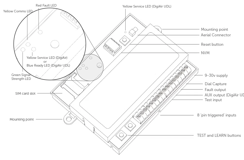
Dimensions | 71mm (h) x 111mm (w) x 18mm (d) | ||||||||||||||||||
Weight | 65g including NVM and SIM | ||||||||||||||||||
Temperature | -20C to +60C transit, -10C to +50C operating | ||||||||||||||||||
Humidity | 0 – 80% non – condensing | ||||||||||||||||||
Mounting | Any orientation | ||||||||||||||||||
Warranty | 5 years | ||||||||||||||||||
Power Requirement | 9.0v – 30.0v | ||||||||||||||||||
Current Consumption | Quiescent = 20 mA Signalling = 200 mA | ||||||||||||||||||
LED Indications |
| ||||||||||||||||||
Radio Path | 3G/GPRS service on a GSM network | ||||||||||||||||||
Aerial | 50 ohm (nominal) on MMCX socket | ||||||||||||||||||
Operation Method | Store and forward | ||||||||||||||||||
CIE Interconnections | Input triggering (Standardised Parallel) Analogue (Dial Capture) | ||||||||||||||||||
RCT Protocols | Fast Format/Contact ID/SIA | ||||||||||||||||||
Input Terminals | Max +30v, Min 0v DC (reference supply 0v terminal) 100k pull-up resistor to +5v | ||||||||||||||||||
Low Battery | 9.8v falling, 12.0v recovery | ||||||||||||||||||
Outputs | Changeover contacts, Max 60v, Max 100mA | ||||||||||||||||||
User Serviceable Parts | There are no user serviceable parts within the DigiAir or DigiAir UDL | ||||||||||||||||||
Standards | Suitable for use in alarm systems complying to: EN50136-1:2012 SP3 SSF 114 v2 Larmklass 2 EN50131-10 Type Y ATS Classification: EN50136 ATS5/SP3 ATS 5 parameters: D3/M3/T4/S2/I3/A3 | ||||||||||||||||||
Environmental | EN50136/EN50131 Environmental class 3 Device should not come into contact with water | ||||||||||||||||||
Emissions | EN55022 | ||||||||||||||||||
Installation | The CS5601/5600 shall be Installed by a service person and be powered by a Limited Power Source in accordance with Clause 2.5 of EN 60950-1 or equivalent, not exceeding the maximum voltage of 30 Vdc, capable of delivering a minimum current of 150mA and be current limited (fused) to 1A. It shall be installed inside an enclosure of another I&HAS component which shall be that of a CIE conforming to EN 50131-3, or a PSU conforming to EN 50131-6.EN55022 |
DigiAir:

LED Indications
LED LABEL | DESCRIPTION | LED STATUS | |||
On | Flashing | Off | Other | ||
Green | Signal Strength | Strong Signal Strength | Acceptable Signal Strength | Low Signal Strength, not acceptable | LED off and Fault LED on indicates no signal |
Yellow | Communications | Input is triggered or Dial Capture is in progress | Sending a message to Gemini and ARC | No communication is in progress | Rapidly flashes to show successful communication |
SVC | Network Status | Radio module initialising and registering to network | SIM card registered on network | There is insufficient power or no power connected to the DigiAir | Rapid flashing indicates unit is not registered to network |
Red | Fault | Fault present see troubleshooting section | NVM contains factory defaults | No faults exist | On for 2 seconds indicates communication failure |
Blue (DigiAir UDL) | Ready | Unit is ready to send messages to Gemini and ARC | N/A | Unit is busy and not ready to send new messages | LED off and Fault LED on indicates programming file is yet to be downloaded (usually takes 5-8 mins from power up with good signal) |
LED FAQs
Q. The Red Fault LED is continuously flashing, what does this mean?
A. This happens when the unit is first powered and needs to download its configuration file from the Gemini Platform which can take up to 5 minutes. You must ensure that the Green Signal LED is either flashing or is on constantly, which indicates the unit is connected to the mobile network.
Q. The DigiAir repeats the ‘power-up’ sequence but never completes it.
A. The power supply has a low output voltage or is unable to supply the current required by the DigiAir when it is activated. Check the power supply with a multimeter. Also, test the DigiAir when powered by a ‘known good’ 12v battery.
Q. The Red Fault LED is on, what is the problem?
A. This indicates the unit cannot operate correctly due to low power or there is a radio fault. Check that the power to DigiAir is between the recommended levels 10-30v DC. If this is correct then the fault will be due to network signal which may be solved by relocating the antenna.
Q. Triggering via ‘Dial Capture’ does not seem to work.
A. Panel may not be compatible or is configured to send a protocol that DigiAir does not recognise. If available check the control equipment programming and select SIA or Contact ID as the signalling format.
Q. The ARC is not receiving messages.
A. Where the correct encrypted acknowledgement signal is not received from the receiving equipment, the DigiAir will repeat the call process for a pre-set number of attempts or until the call is successfully passed to the receiving equipment. If the message cannot be successfully passed, then upon request the fault output may be programmed to operate. In this instance, please contact CSL Technical Support.
Panel Compatibility
DigiAir UDL Panel Compatibility
Panel manufacturers and models that are currently compatible with DualCom GradeShift & DigiAir UDL for alarm reporting using Dial Capture. Panel compatibility is an evolving process with new manufacturers being added regularly. Please call Technical Support for the latest updates on: UK: +44 (0) 1895 474 444 or Ireland: 1800 855 695.
Panel | Model | Connection to Panel | Alarm Signalling Format | RSD |
Honeywell Galaxy G3 v5.6 up | 48 | Dial Capture | Fast Format (FF) / Contact ID (CID) / SIA | Alarm Reporting |
Honeywell Galaxy G3 v5.6 up | 48, 144, 520 | RS485 | SIA | Alarm Reporting |
Honeywell Dimension v6 up | 48, 96, 264, 520 | RS485 | SIA | Alarm Reporting, UDL and Panel Initiated |
Honeywell Dimension v6 up | 48, 96, 264, 520 | Dial Capture | FF / CID / SIA | Alarm Reporting, UDL and Panel Initiated |
Honeywell Flex FX050 | E2 | RS485 | SIA | Alarm Reporting, UDL and Panel Initiated |
Honeywell Galaxy G2 v1.52 up | 144 | Dial Capture (requires external Honeywell digi) | FF / CID / SIA | Alarm Reporting |
Honeywell Galaxy | 16+ | Dial Capture | FF / CID / SIA | Alarm Reporting |
Honeywell Galaxy | 18,60 | RS485 | SIA | Alarm Reporting |
Castle Caretech/Pyronix | Enforcer | Dial Capture | FF / CID / SIA | Alarm Reporting, UDL and Panel Initiated |
Castle Caretech Euro | 46, 76 | Dial Capture | FF / CID / SIA | Alarm Reporting, UDL and Panel Initiated |
Castle Caretech Euro ONE | 76 | Dial Capture | FF / CID / SIA | Alarm Reporting, UDL and Panel Initiated |
Texecom Premier | 16, 24, 48, 88, 168 | Dial Capture | FF / CID / SIA | Alarm Reporting, UDL and Panel Initiated |
Texecom Premier Elite | 12, 16, 24, 48, 88, 168, 640 | Dial Capture | FF / CID / SIA | Alarm Reporting, UDL and Panel Initiated |
(Cooper) Menvier | M800, M1000, M2000 | Dial Capture | FF / CID / SIA | Alarm Reporting |
(Cooper) Menvier | 30, 40, 100, 300 | Dial Capture | FF / CID / SIA | Alarm Reporting |
(Cooper) Scantronic On wall | 9752, 9853, 85EN | Dial Capture | FF / CID / SIA | Alarm Reporting |
Cooper i-On | 30, 40, 50, 160 | Dial Capture | FF / CID / SIA | Alarm Reporting |
Risco Prosys | 16, 40, 128 | Dial Capture | CID / SIA | Alarm Reporting |
Risco Eurosec CPX v4.0 | CPX | Dial Capture | FF / CID / SIA | Alarm Reporting |
Risco Litesys | Litesys 2 | Dial Capture | SIA | Alarm Reporting and UDL |
Risco Wisdom | Wisdom | Dial Capture | CID / SIA | Alarm Reporting |
Risco Agility | Agility 3 | Dial Capture | CID / SIA | Alarm Reporting and UDL |
Risco GuardTec | 480/490/590/593/ 595/600/601/800 | Dial Capture | FF / CID / SIA | Alarm Reporting |
Visonic PowerMax | Complete, Pro | Dial Capture | FF / CID / SIA | Alarm Reporting |
Visonic PowerMaster | 10, 30 | Dial Capture | FF / CID | Alarm Reporting |
Guardall | PX48i, PX500 | Dial Capture | FF / SIA | Alarm Reporting |
HKC | 1070 | Dial Capture | SIA | Alarm Reporting |
HKC SecureWatch | 16/120 | Dial Capture | FF / CID / SIA | Alarm Reporting |
HKC Quantum | 70 | Dial Capture | FF / CID / SIA | Alarm Reporting |
InterLogix (Aritech) | Advisor | Dial Capture | CID / SIA | Alarm Reporting |
Siemens (Europlex) | SPC6330 | Dial Capture | FF / CID / SIA | Alarm Reporting |
UTC | ATS1000A-IP, ATS2000A -IP | Dial Capture | CID / SIA | Alarm Reporting |
UTC | Aritech CD103, CD1512, CD6103, CD6203, CD7212, CD9103, CD9512, CD14803 | Dial Capture | CID / SIA | Alarm Reporting |
FAQs
Can I use Dial capture with a DigiAir?
Yes! Both the DigiAir and DigiAir UDL support Dial Capture with compatible panels.
Why is the red FLT (Fault) LED on?
The Fault LED indicates a problem with the DigiAir. To understand the type of fault, press and release the LEARN button. This will cause the Red Fault LED to flash a few times.
- 1 flash = NVM chip faulty or missing.
- 2 flashes = Supply voltage is low (below 9vdc).
- 3 flashes = No radio signal. Digiair is unable to register on the network. Relocate the aerial to improve the signal.
- Flashing on and off continuously = The DigiAir is not configured. If it is still flashing after 10 minutes. Please contact the Technical Support team.
For further support you can contact our Technical Support team on +44 1895 474 444 or email us at support@csl-group.com.
Why are my alarms not going through (Serial RS485)?
The Serial RS485 connection is only compatible with the DigiAir UDL. The standard DigiAir does not support this connection method.
The RS485 connection wires from your panel data line to the DigiAir UDL pins 7 & 8. In addition to your panel needing to be programmed for the RS485 connection, the DigiAir UDL also needs to be configured by our Technical Support team.
You can call our Technical Support team on +44 1895 474 444 or email them at support@csl-group.com.
How can I check the signal strength on my DigiAir?
The green GRN (SIG for UDL variant) labelled LED will provide an indication for the level of signal strength the DigiAir is receiving.
- Off = Poor to No Signal.
- Flashing on and off = Acceptable signal strength. You can multiply the flashes by 7 to get an estimate on the signal strength percentage.
- On solid = Good signal strength.
Why are my alarms not going through (Hardwired pins)?
The pins on the DigiAir require negative voltage to trigger. Ensure your panel outputs are set for negative and try again.
Important Note: You can short directly into one of the pins on the DigiAir to test if it is working. Simply wire a single core wire into the negative on the DigiAir and wire the other end of the wire into the DigiAir pin you would like to test. This should send an alarm through on that pin.
Where do I connect the RS485?
The RS-485 connection can accept alarm information as well as providing Remote Servicing & Diagnostics (RSD) functionality.
The RS485 connection wires from your panel data line to the DigiAir UDL pins 7 & 8. In addition to your panel needing to be programmed for the RS485 connection, the DigiAir UDL also needs to be configured by our Technical Support team.
.
You can call our Technical Support team on +44 1895 474 444 or email them at support@csl-group.com.
Why can I see the comms light flashing when no signals are being transmitted?
This is normal. The unit is sending a poll call through to the monitoring station.
Why are my alarms not going through (Dial Capture)?
Dial Capture is Plug ‘n’ Play on the DigiAir. Meaning the DigiAir does need any changes made to it to work with Dial Capture.
Dial Capture wires from your panel Digi to the DigiAir A2 and B2 terminals. You must have an account number and dummy phone number programmed into your panel. The DigiAir will generate around 45v to 50v on the A2 and B2 terminals. When you send an alarm through from your panel, your panel Digi should draw on that voltage and drop it to around 6v to 8v. Measuring for this voltage drop on the A2 and B2 terminals is a good way to check if your panel is initiating the alarms over the Dial Capture connection.
The format you send your alarms on may not be (or may no longer be) supported. For example, if you are sending your alarms over Dial Capture in SIA, try using a different format.
For further support please contact our Technical Support team on +44 1895 474 444 or you can email us at support@csl-group.com.
PSU Guide
Installation
Refer to the DigiAir Quick Guide for triggering and Dial Capture connections.
Where the CS1510 will be used with a small CIE, the CIE is unlikely to have 3 separate fault inputs. This diagram shows how to wire all of the PSU & DigiAir fault outputs (Mains, Battery & DigiAir) to one panel fault input. Refer to the DigiAir Quick Guide for triggering and Dial Capture connections.
Main failure and mains restore (on the AC FLT output) will be reported by the PSU to the CIE in less than 10 seconds. Note that Mains failure reporting (by the CIE) to the ARC may be delayed for up to 1 hour EN50131 standard. Refer to the CIE manual for its programming/setup details. When the wiring between the PSU, CIE and DigiAir is completed, plug the battery into the BAT connector on the PSU board and connect mains power to the L, N & E terminals.
The CS1510 is a compact type A Power Supply (PSU) with battery back-up that is designed to house and power a DigiAir, and to be mounted with its associated Control Panel (CIE). The CS1510 Power Supply is suitable for use in systems installed to conform to PD 6662:2010 at Grade 1 & 2, and environmental class 1 & 2.
The CSL5652/5653 is the PSU with a DigiAir already fitted with its power wiring connected. The CS1510 is the same PSU but is supplied without a DigiAir.
This PSU is designed to supply power to a DigiAir only. Do not use the PSU to supply power to a DigiAir AND
other equipment.
When fitting a DigiAir into the PSU ensures that the DigiAir’s break-off mounting lugs are removed.
Ensure that the PSU’s + and – 12 volt output is connected to the DigiAir’s + and – supply input.
The ‘normally closed’ PSU outputs must be wired to the CIE inputs so that CIE setting may be inhibited by:
- TAMP terminals
- A tamper fault (i.e. the PSU lid is removed)
- AC FLT terminals
- Prime power (mains, EPS) fault
- FLT terminals
- Alternate power (battery, APS) low voltage or failure
- COM & NC terminals on DigiAir
- DigiAir (ATS) path or communications fault.
Do not run wiring under the PSU board.
LED Indications
LED Label | LED STATUS | ||
ON | Flashing | OFF | |
Red FLT LED | Battery disconnected Battery charge fail Over voltage output Low voltage output | – | No faults |
Green OK LED | Battery power OK Mains power OK | Battery power OK but no mains power | No battery power and no mains power |
Specifications
Manufacturer | CSL |
Part Numbers | CS1510 – PSU (PSU only) CS5652 – PSU + DigiAir UDL UK/Ire CS5653 – PSU + DigiAir UDL EU CS0710 – Replacement battery |
Installation Standard | This PSU is designed to meet the requirements of: EN50131-1:2006 + A1:2009, Grade 1 & 2 EN50131-6:1998 EN50131-10:2014 EN50136-2:2013, SP1 & SP2 EN50136:1998 Grade 2 ATS2 = D2, M2, T2, S0, I0 EN50136:1998 Grade 2 ATS3 = D2, M2, T2, S1, I1 PD6662:2010 PD6662 IA 1501:2015 |
EMC standard | EN 61000-6-3 EN 50130-4:2011 |
Electrical safety st’d | EN 60065:2014 or EN62368-1:2014 |
PSU Type | Type A (EN50131-6:1998) |
Environmental Class | 1 & 2, Indoor Heated & Indoor General |
Temperature Range | -10 to +40 Centigrade |
Humidity | Less than 75%, non-condensing |
Mains supply | 230v +/- 10% AC, 50Hz +/- 5Hz |
Max output current | No more than 1.00A may be continuously drawn from the PSU |
Output ripple | At the max output current and 90% mains supply, max ripple = 50mV |
Low Voltage fault | The FLT output will activate when the output voltage is below 9.60 volts |
AC FLT output | Normally closed (no mains fault), clean contacts. 60 volts, 100mA max |
FLT output | Normally closed (no battery fault), clean contacts. 60 volts, 100mA max |
TAMP output | Normally closed (with lid fitted), clean contacts. 60 volts, 500mA max |