
Introduction
Initial Setup
Configuration
Checking The Installation

Troubleshooting


Technical Specifications
| Dimensions | LAN/Radio, Radio or LAN: 70 mm (h) x 125mm (w) x 16mm (d)Radio/Radio: 75 mm (h) x 125mm (w) x 16mm (d) |
| Weight | TBC |
| Temperature | -10 °C to + 55 °C |
| Humidity | 0 – 90% non-condensing |
| Mounting | TBC |
| Warranty | 5 years |
| Power Requirement | 10 – 30 Volts DC
To maintain compliance with electrical safety requirements, the DualCom Pro 4 shall always be powered from a fused SELV supply with the following ratings:
If the power source is not limited to these values, a suitably rated fuse must be fitted in line with the positive connection from the power source. The SPT will shut down on detection of a low supply voltage of 7.6 V DC ± 0.5 V DC. |
| Current Consumption | Radio only:
LAN/Radio:
|
| Radio Path | 2G, 4G |
| Output Ratings | Maximum applied voltage = 35V Maximum current = 150mA |
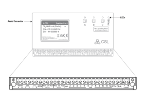
| Aerial | 50 ohms (nominal) on MMCX socket |
| Operation Method | Pass Through |
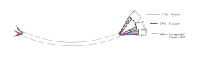
| CIE Interconnections | Input triggering (standardised parallel), Dial Capture, RS232, RS485, TTL, Ethernet. The connectors allow the use of 16-28 AWG cable. |
| RCT Protocols | SIA |
| Input Terminals | Max +30v, Min 0 volts DC (reference supply 0v supply) 100k |
| User Serviceable Parts | There are no serviceable parts within the DualCom Pro Range |
| Environmental | Class II |
| Applicable Standards | Suitable for use in alarm systems complying with:
Emissions Standard
Environmental Standard
ATS Configuration EN 50131-10:2014 Type Y
|
Safety Information:
This equipment is intended for professional installation only.
The DualCom Pro 2/3/4 shall be installed within an enclosure or control panel that provides compliance with the applicable system safety standards. The device is designed to be powered from a limited power source (SELV).
Installation and operation shall be carried out in accordance with the instructions provided. Incorrect installation or operation may compromise safety and regulatory compliance.
The product contains radio transmitters. It shall be installed and operated in accordance with the instructions to ensure compliance with applicable electromagnetic field (EMF) exposure limits.
Do not attempt to open, modify, or repair this equipment.
Regulatory Compliance – Radio Equipment Directive (RED)
Hereby, CSL DualCom Ltd declares that the DualCom Pro 2/3/4 radio equipment type is in compliance with Directive 2014/53/EU (Radio Equipment Directive).
The product fulfils the essential requirements of the Directive:
- Article 3.1(a): Health and safety
- Article 3.1(b): Electromagnetic compatibility
- Article 3.2: Effective use of the radio spectrum
The full text of the EU Declaration of Conformity is available from the manufacturer (CSL DualCom Ltd) here.
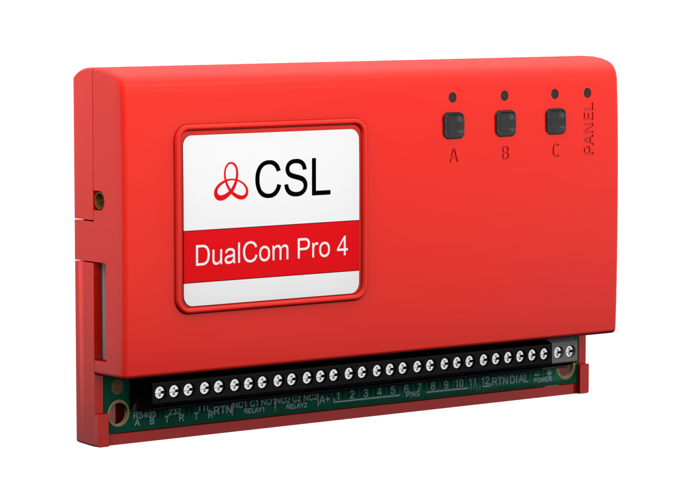
DigiAir Pro 4
| PATH | AVAILABLE GRADES | WHAT’S IN THE BOX | PART NUMBER |
| Radio | SP2 | DigiAir Pro 4, serial cable & small aerial | CS.51.R2 |
| LAN | SP2 | DigiAir Pro 4, serial cable, Ethernet cable | CS.51.L2 |
GradeShift Pro 4
| PATH | AVAILABLE GRADES | WHAT’S IN THE BOX | PART NUMBER |
| LAN + Radio | DP2, DP2+, DP3, DP4 | GradeShift Pro 4, serial cable, aerial and ethernet cable | CS.53.LR2
CS.53.LR2P CS.53.LR3 CS.53.LR4 |
| Radio + Radio | DP2, DP2+, DP3 | GradeShift Pro 4, serial cable, 2 x aerial | CS.53.RR2
CS.53.RR2P CS.53.RR3 |
 |
| 25 |
| DualCom Pro 4 |
| CSL DualCom Ltd.
Building 4, Croxley Park, Hatters Lane, Watford, WD18 8YF |
| Fire detection and fire alarm systems / Alarm transmission and fault warning routing equipment
EN 50131-10:2014 EN 50136-1:2012/A1:2018 EN 50136-2:2013 PD6662:2017 / PD6669:2017 |
| Type of transmission system: Type 1
SP5 / DP4 Security Grade: 1- 4, depending on the I&HAS housing in which it is installed. |
| Environmental Class: II |
| www.csl-group.com |