

A charger may appear available even when a driver cannot start or complete a session. Wider network coverage can reduce local signal problems, but it does not necessarily protect against failures elsewhere in the communications path.
The appropriate connectivity architecture therefore depends on the operational and commercial consequences of losing service.
Who this FAQ is for
This FAQ is written for the teams responsible for charger reliability, uptime, procurement and fleet readiness.
- Charge point operators evaluating connectivity for new or existing estates.
- Fleet and depot operators assessing charging reliability and vehicle readiness.
- Charge point installers and site hosts specifying connectivity for a site.
- Local authorities and landlords setting or monitoring uptime obligations.
- Procurement teams comparing connectivity options against operational and regulatory requirements.
Connectivity priorities by site type
The table below outlines the typical connectivity priorities for different charging environments. The appropriate approach will depend on the site design, available bearers and the operational consequences of losing service.
| Site type | Typical connectivity priority |
|---|---|
| Single AC or workplace charger | Managed cellular connectivity, monitoring and remote diagnostics |
| Public rapid charger | Resilient cellular connectivity, core diversity and active monitoring |
| Ultra-rapid hub | Multiple independent bearer paths and protection against shared failures |
| Fleet depot | Resilient primary connectivity, cellular backup and local fallback capability |
| Rural or remote site | Resilient multi-network cellular connectivity, remote diagnostics and a contingency bearer |

1. The EV transition
The market context: how fast the network is growing, why charging reliability remains central to the adoption debate, and what the shift means for fleets.
The CSL Electric Vehicle Transition Executive Summary sets out the full market analysis, and the four-part Transitioning to Electric Vehicles series covers the underlying themes in depth.
How quickly is the UK’s public charging network growing?
Zapmap recorded 121,171 public EV chargers across 46,731 locations at the end of June 2026, a 10 per cent year-on-year increase. Ultra-rapid chargers rated at 150 kW and above reached 13,996, up 37 per cent year on year1.
Growth is increasingly concentrated in higher-powered and en-route charging. These sites can carry greater commercial exposure when downtime affects high-utilisation chargers or several bays sharing the same dependency. Zapmap and the Department for Transport publish on different schedules and present their figures through different statistical releases, so changes over time are best assessed within a consistent series.
FURTHER READING Resilient Connectivity for EV Charging Infrastructure, the CSL white paper on what this growth means for reliability.
What is the Zero Emission Vehicle (ZEV) Mandate, and what does it require?
The ZEV Mandate sets rising annual targets for the proportion of each manufacturer’s new car and van registrations that must be zero-emission. For new cars the target is 28 per cent in 2025 and 33 per cent in 2026, rising to 80 per cent by 20306.
New van targets follow a lower path, at 16 per cent in 2025 and 24 per cent in 2026, and heavy goods vehicles sit outside the Mandate. The mandate reaches 100 per cent for new cars and vans in 2035. Banking, borrowing, trading and other compliance flexibilities can affect how an individual manufacturer meets the headline target in a particular year. As a result, the proportion of zero-emission vehicles registered in the market may differ from the annual headline target. For charge point operators, more electric vehicles on the road means rising demand for public and depot charging, and greater commercial and regulatory weight on charger reliability.
FURTHER READING EV Commercial Fleet Transitions and the Challenges for HGVs and Rapid Charging Infrastructure (Article 2 in the CSL Transitioning to Electric Vehicles series).
Why is charging reliability a major barrier to wider EV adoption?
Because drivers still encounter chargers that cannot complete a session. In J.D. Power’s 2025 US EVX Public Charging Study, 14 per cent of EV owners reported visiting a public charger but being unable to charge, an improvement from 19 per cent in 20243.
CSL’s review of published reliability studies indicates that reported technical availability can overstate driver session success, with gaps of 10 to 20 percentage points appearing in some of the datasets examined5. Connectivity is a frequent and easily overlooked cause of that gap, so improving reliability means addressing the communications path, not only the hardware.
FURTHER READING The evidence base is set out in Resilient Connectivity for EV Charging Infrastructure.

2. EV charging fundamentals
What are the main types of EV charger?
Chargers are grouped by power. Using the current DfT bands, these are standard (3 to under 8 kW), standard plus (8 to under 50 kW), rapid (50 to under 150 kW) and ultra-rapid (150 kW and above); depot and workplace charging are use cases that span several bands rather than a separate power class.
Chargers below 50 kW continue to make up the majority of the UK public charging estate and are concentrated in longer-dwell settings, including destination, workplace and residential charging2. High-utilisation ultra-rapid hubs can carry substantial revenue exposure because several high-powered bays may share the same connectivity dependencies. Each type has a different connectivity priority, which Section 5 maps in detail.
FURTHER READING EV Charging, Power Delivery Systems and Smart Infrastructure (Article 3 in the series) covers charging systems, standards, V2G and grid integration.
What is EV connectivity, and why do managed chargers depend on it?
EV connectivity is the secure communications layer that lets a charger operate as a managed, monitored, revenue-generating service.
It supports charger-to-back-office communication over OCPP, payment authorisation and transaction exchange, driver-app, RFID and roaming workflows, status reporting, remote diagnostics, firmware management and load-management signals. A charger with power but without communications may be unable to authorise a driver, take payment, report its true status or receive remote support.
FURTHER READING EV Connectivity, EV Routers and EV SIM Cards, the CSL FAQ covering definitions, options and a full buyer checklist.
What is OCPP?
The Open Charge Point Protocol is an open application protocol for communication between a charge point and a Charge Station Management System (CSMS).
OCPP supports authorisation, session start and stop, meter values, status notifications, configuration changes and firmware updates. Live OCPP exchange depends on the underlying connectivity: when the network path is unstable, live messages may be delayed or fail to reach the management system, reducing the operator’s real-time visibility and ability to manage the charger remotely. Some chargers support limited offline operation, using cached credentials or an offline-authorisation policy to start sessions and reconcile records once the connection returns, but this is a fallback with limits rather than a substitute for a reliable connection.
What is the difference between an EV SIM card and an EV router?
An EV SIM card provides cellular identity and data service, typically embedded in the charger. An EV router is site-level hardware that connects one or more chargers, with multiple WAN options, external antennas, VPN routing and failover.
An embedded SIM may be sufficient for an individual AC charger or small workplace installation where the operational consequences of losing connectivity are limited. Router-based architectures suit rapid and ultra-rapid hubs, multi-bay sites, forecourts and fleet depots, where bandwidth, resilience and remote management requirements are higher.
FURTHER READING Full definitions, comparison tables and the buyer checklist are in EV Connectivity, EV Routers and EV SIM Cards.

3. Regulation and how reliability is measured
What do the Public Charge Point Regulations 2023 require?
Under the Public Charge Point Regulations 2023 (PCPR), in-scope charge point operators must achieve an average of 99 per cent reliability across their rapid (50 kW and above) public charging network over each calendar year, alongside applicable requirements covering contactless payment, payment roaming, pricing, helplines and open data4.
In the UK, the Office for Product Safety and Standards acts as the enforcement authority on behalf of the Secretary of State4. The first annual reliability reports, covering the 2025 calendar year, were submitted in January 202610.
The direction internationally is consistent, though the specific obligations differ. The US NEVI programme sets a minimum average annual uptime of greater than 97 per cent per port for federally funded charging7. The EU’s Alternative Fuels Infrastructure Regulation (AFIR) sets deployment, payment, price transparency and open data requirements across member states, rather than a single UK-style operational availability measure8.
Connectivity can materially affect payment, open-data reporting, operational visibility and the driver experience. Qualifying communications network failures may be excluded from the statutory reliability calculation where the operator can provide the required evidence, but this does not remove their operational or commercial impact9.
FURTHER READING The regulatory analysis in Resilient Connectivity for EV Charging Infrastructure.
Why is device uptime not the same as a successful charging session?
Reported charger availability indicates that the unit is being recorded as operational or available. Session success shows whether a driver can authenticate, start charging, pay where required and receive energy.
A charger can appear available even when a payment, authorisation, connector or user-interface fault prevents a session from starting, particularly where the fault is not reflected accurately in the status data available to the management platform. Measuring functional availability can expose a gap between reported availability and the experience of drivers attempting to charge5.
How should operators measure charging reliability?
By session success, not device uptime alone.
The measures that matter alongside uptime are session start success rate, payment success rate, OCPP availability, mean time to detect and repair faults, remote fix rate, and the number of chargers affected by shared-dependency failures. The last measure is easy to overlook but can be highly consequential, because one shared-dependency event may affect many chargers simultaneously.
FURTHER READING A fuller measurement framework, including how to tell a charger fault from a connectivity fault, is in EV Connectivity, EV Routers and EV SIM Cards.

4. The cost of connectivity downtime
How much revenue is at risk when a charger cannot communicate?
A simple model can estimate the gross charging revenue at risk: indicative charging revenue at risk = power (kW) × utilisation × tariff (£ per kWh) × downtime hours5.
In this calculation, utilisation is expressed as the proportion of the charger’s rated capacity that would otherwise have been delivered during the affected period.
CSL’s white paper applies this model using published GFI utilisation benchmarks, RAC Charge Watch and Zapmap Price Index tariff data to estimate downtime exposure across charger types, from destination AC chargers to ultra-rapid hubs.
Within the model, higher power and utilisation increase the rate at which gross revenue exposure accumulates, while a shared site dependency can multiply the exposure across several bays. Actual exposure depends on the charger, utilisation, tariff, outage duration and site conditions, so the figures are illustrative rather than guaranteed outcomes.
FURTHER READING The full financial analysis, including scenario modelling by estate size and connectivity spend, is in Resilient Connectivity for EV Charging Infrastructure.
How does the cost of downtime differ across charger types?
The headline cost per hour rises with power, but the shape of the loss differs by setting5.
- Destination and residential AC: lower revenue per hour, but faults across long-dwell estates can persist undetected, so cumulative losses, support calls and driver frustration build over weeks rather than minutes.
-
Public rapid: immediate driver impact, lost sessions, SLA exposure and potential relevance to PCPR reliability, payment and reporting obligations.
-
Ultra-rapid hubs: potentially high revenue density and correlated exposure across several bays.
A correlated failure can affect every bay that depends on the failed shared service. In one CSL modelled scenario, assumed values for the number and power of chargers, utilisation, tariff and outage duration produce an estimated gross revenue exposure above £100,000 during an estate-wide carrier failure. This is an illustrative model output, not an observed loss from a live charging estate.
- Fleet depots: the cost is vehicle grounding rather than energy revenue. Using the assumptions in CSL’s illustrative model, grounding a 12-van depot for a shift produces an estimated operational exposure of approximately £6,300 per incident, giving annual exposure of roughly £12,600 to £18,900 if such outages recur two to three times a year; this scales with fleet size, the per-van cost of lost availability and outage frequency.
FURTHER READING Worked figures by charger type sit in Resilient Connectivity for EV Charging Infrastructure.
What is the difference between independent and correlated outages?
An independent outage affects a single device. A correlated outage can affect many chargers at once because they share a common dependency.
Independent outages include local signal loss, a failed modem, a damaged antenna or a local configuration issue. Correlated outages occur when multiple chargers share a dependency that fails, such as a mobile core, authentication platform, payment gateway, cloud region or certificate authority. Under its stated assumptions, CSL’s illustrative modelling shows how a shared-dependency failure can create greater revenue exposure than numerous isolated device faults5.
Beyond lost charging revenue, what else does downtime cost?
In some incidents, secondary costs may exceed the direct charging revenue lost during the outage.
They include SLA penalties and driver compensation, regulatory reporting or compliance exposure, contract and landlord risk, and reputational damage that pushes drivers towards competing sites. Operationally, connectivity faults generate avoidable engineer visits, including the familiar “no fault found” call-out where the problem sits in the communications path rather than the unit, and each unnecessary site visit adds cost without fixing the underlying cause.

5. Building resilience: the CSL approach
Why coverage alone is not resilience, and how CSL’s DualCore®, rSIM® and PACE architectures address the failure modes that matter.
Are multi-network SIMs enough for critical chargers?
They improve radio coverage, but coverage is not the same as resilience.
A multi-network service can reach several radio access networks while still routing traffic through a shared mobile core. If that shared core or its associated service path fails, access to additional radio networks may not restore service because the traffic still depends on the affected upstream infrastructure. For critical charging, the question is whether a solution is multi-RAN only or genuinely core-diverse, so procurement teams should verify whether the service provides independent core paths.
What is dual-core connectivity?
An architecture that provides two independent mobile-core paths, allowing communications to switch from one supported path to the other when defined failure conditions are detected.
CSL provides this as DualCore®. This is the practical difference between core diversity and a multi-RAN service that may route all available radio networks through a shared core. With DualCore, failure of one supported mobile-core path can trigger a switch to the alternative path. This can restore communications without a site visit where the device, SIM, network configuration and remaining service dependencies continue to operate correctly.
FURTHER READING The architecture comparison in Resilient Connectivity for EV Charging Infrastructure.
What is rSIM, and how does it complement eSIM remote provisioning?
rSIM® is CSL’s resilient SIM architecture, using two independent core-network profiles on a single SIM and on-SIM logic to monitor connectivity and initiate a switch between them.
Because the failover decision is made locally, the SIM does not rely solely on a remote platform instruction to respond to a loss of service. This complements, rather than replaces, standards-based remote SIM provisioning. GSMA remote provisioning architectures govern the secure download, enablement and management of operator profiles, while rSIM’s resilience logic governs how available connectivity profiles are used when service conditions change. The two capabilities address different requirements: provisioning provides lifecycle flexibility, while rSIM provides autonomous failover between the available paths.
FURTHER READING The rSIM solution overview and the Evology Charging case study.
What is PACE?
PACE, meaning primary, alternate, contingency and emergency, helps to conceptualise CSL’s layered multi-bearer approach for sites where the consequences of losing connectivity justify several independent paths.
A deployment may combine a primary fixed or bonded broadband service with separate cellular paths and a satellite contingency, with the precise bearer order determined by the site design. CSL Outpost can combine multiple 4G or 5G modules with satellite, fibre or wireless connections, using SDN technology to manage the available paths and failover.
This makes the approach a potential starting point for ultra-rapid hubs, fleet depots and other sites where a shared connectivity failure would have significant operational or contractual consequences.
Which connectivity architecture suits each charger type?
The appropriate connectivity architecture depends on more than signal strength. It should reflect the site’s operational requirements, shared dependencies and the consequences of losing service.
An illustrative starting point by charger power band, showing typical priorities.
| Charger type | Connectivity priority | Illustrative CSL starting point |
|---|---|---|
| Standard (3 to under 8 kW) | Fault detection and remote management across long-dwell estates. | Managed SIM with monitoring; rSIM® where uptime matters. |
| Standard plus (8 to under 50 kW) | Coverage in marginal locations, plus remote reset. | rSIM with DualCore resilience; site Ethernet or Wi-Fi as an additional path where available. |
| Rapid (50 to under 150 kW) | Avoiding correlated outages across a shared gateway; SLA compliance. | Wired backhaul with resilient cellular backup delivered through rSIM or a DualCore router, supported by payment and OCPP monitoring. |
| Ultra-rapid (150 kW and above) | Potentially high revenue exposure and correlated risk across several bays. | PACE architecture: primary fixed or bonded broadband, separate cellular paths and an optional satellite emergency path, configured according to the site design. |
| Fleet depot (use case) | Vehicle readiness and smart-charging continuity. | Wired primary connectivity with resilient cellular backup delivered through rSIM or a DualCore router, optional satellite contingency and a local fallback scheduler. |
| Rural or remote | Remote fix to avoid costly site visits; a contingency path. | rSIM with suitable cellular coverage and core network resilience, satellite contingency and remote diagnostics. |
These are illustrative starting points. The final architecture depends on the site survey, the bearers available, device configuration and the operational consequences of failure at that site.
FURTHER READING The full mapping, with typical settings and offline-mode guidance, is in EV Connectivity, EV Routers and EV SIM Cards.
Where has CSL’s approach been deployed?
A good example is Evology Charging integrating CSL’s rSIM across its UK charging network.
The deployment is designed to support charging station operations across areas with variable network coverage, while private APN connectivity protects payment and monitoring traffic. The architecture provides a connectivity foundation intended to support the continued expansion of Evology’s connected charging network.
FURTHER READING The Evology Charging case study.
6. The CSL EV library
The published white papers, blogs and case studies referenced throughout this FAQ.
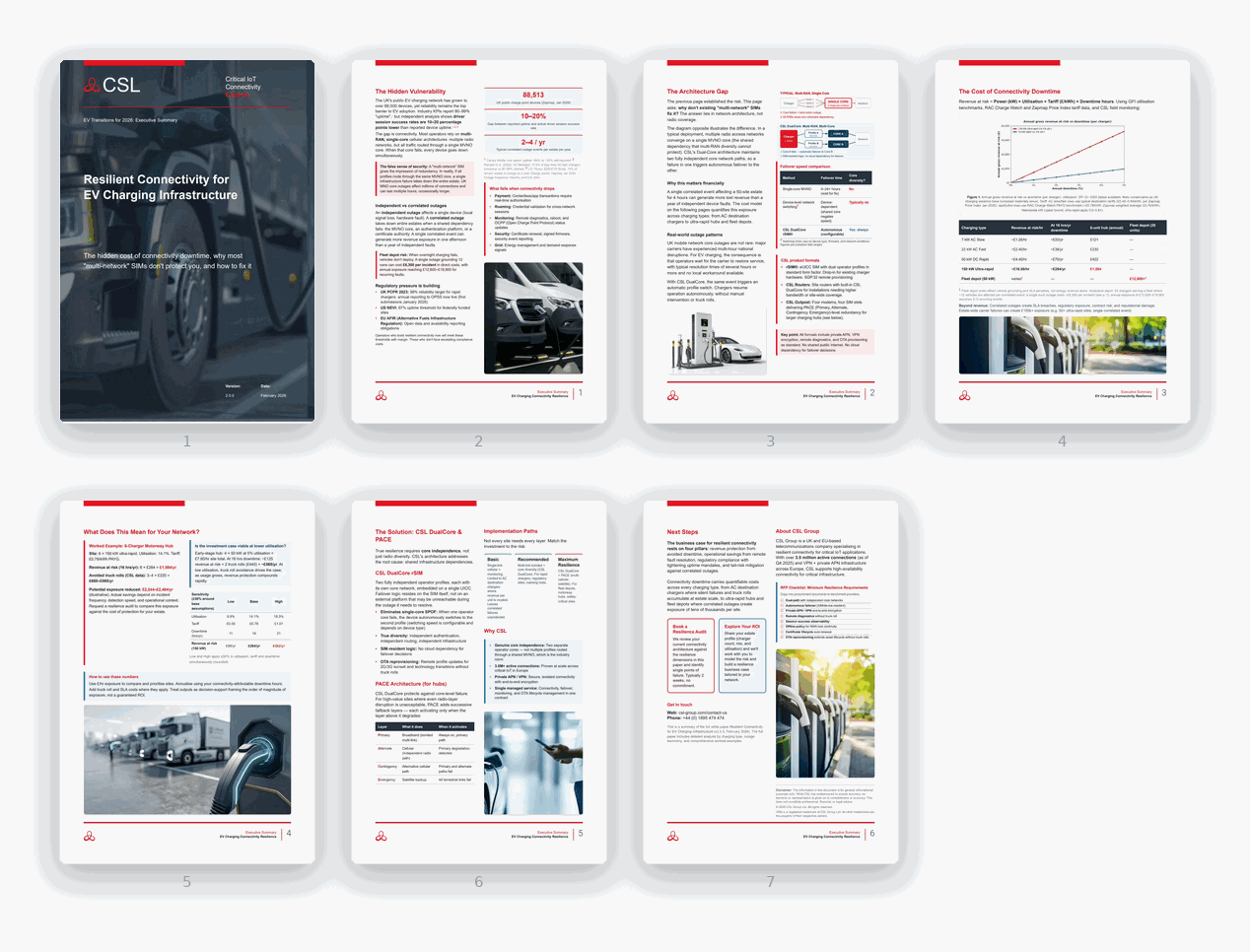
Resilient Connectivity for EV Charging Infrastructure
The technical and economic case for resilient EV charging connectivity, including the gap between reported uptime and session success, downtime modelling, the resilience playbook, and CSL’s DualCore, rSIM and PACE architectures.
The Electric Vehicle Transition: Executive Summary 2026
The market analysis behind Section 1, including charging-network growth, the ZEV Mandate, EV adoption and the reliability challenge.
EV Connectivity, EV Routers and EV SIM Cards
Definitions and comparisons of connectivity options, guidance on distinguishing connectivity faults from charger faults, a buyer checklist and a glossary.
Transitioning to Electric Vehicles
A four-part white paper series covering driving behaviour and telematics, commercial fleets and HGVs, charging and smart infrastructure, and the roles of AI and machine learning.
- Article 1: The Impact of EV Driving Behaviours on Telematics and Road Safety.
- Article 2: EV Commercial Fleet Transitions and the Challenges for HGVs and Rapid Charging Infrastructure.
- Article 3: EV Charging, Power Delivery Systems and Smart Infrastructure.
- Article 4: The Future of Telematics: The Roles of AI and ML in ADAS, EVs and AVs.
How a UK charge point operator deployed rSIM to support resilient connectivity, private APN security and expansion of its connected charging network.
Solution pages
rSIM · IoT Routers · IoT SIM · CSL Broadband · CSL Satellite · CSL Signal Analyser 2
7. Explore the wider EV transition
What are the main challenges for commercial fleets and HGVs moving to electric?
Battery electric vehicles are the leading technology for decarbonising commercial fleets, but the transition depends on rapid charging infrastructure at strategic locations, continued gains in battery range, supportive regulation and connected telematics.
For heavy goods vehicles, alternatives such as electric roadway systems and hydrogen fuel cells are also being assessed, and off-grid operations in quarries, mines and remote sites raise their own power and connectivity questions. Depot readiness matters as much as vehicle choice: if overnight charging fails, vehicles are not ready for their departure windows and the cost is measured in missed routes rather than lost energy revenue.
FURTHER READING EV Commercial Fleet Transitions and the Challenges for HGVs and Rapid Charging Infrastructure (Article 2 in the CSL Transitioning to Electric Vehicles series).
How do EV driving behaviours affect telematics and road safety?
EVs change how vehicles accelerate, brake and recover energy, which changes both driving patterns and the data fleet operators need.
Instant torque, regenerative braking and range management alter driver behaviour compared with combustion vehicles. Telematics platforms therefore need EV-specific inputs, including state of charge, energy consumption and charging events, to coach drivers, plan duty cycles and maintain safety and efficiency across a transitioning fleet.
FURTHER READING The Impact of EV Driving Behaviours on Telematics and Road Safety (Article 1 in the series).
What role will AI, machine learning and autonomous vehicles play?
AI and machine learning underpin advanced driver assistance systems, predictive maintenance and the connectivity demands of increasingly automated vehicles.
5G, edge computing and vehicle-to-everything (V2X) communication support cooperative services and wider situational awareness. They do not replace the immediate, safety-critical control a vehicle performs on board, which must keep working if external connectivity is lost. Over time, vehicles, chargers and infrastructure increasingly behave as one connected system, so the communications layer becomes safety-relevant and commercially relevant without becoming the control path itself.
FURTHER READING The Future of Telematics: The Roles of AI and ML in ADAS, EVs and AVs (Article 4 in the series).
Talk to CSL about resilient charging connectivity
CSL designs connectivity for EV charging as critical infrastructure: DualCore diversity, rSIM autonomous failover, private APN and VPN routing, the PACE multi-bearer stack and monitoring that can be correlated with CSMS and payment data to help explain session failures.
To size the right architecture for your sites, and to model the cost of downtime across your estate, contact the CSL team.
References
- Zapmap, statistics for H1 2026 (end June 2026).
- UK Department for Transport, Public electric vehicle charging infrastructure statistics (1 April 2026).
- J.D. Power, 2025 US EVX Public Charging Study.
- UK Department for Transport, The Public Charge Point Regulations 2023.
- CSL, Resilient Connectivity for EV Charging Infrastructure (2026): session-success analysis, downtime cost modelling, correlated outage frequency and fleet depot exposure figures, drawing on GFI utilisation benchmarks, RAC Charge Watch and Zapmap Price Index tariff data.
- The Vehicle Emissions Trading Schemes Order 2023 (SI 2023/1394, as amended), which implements the UK Zero Emission Vehicle Mandate.
- US Federal Highway Administration, National Electric Vehicle Infrastructure standards, 23 CFR 680.116 (minimum average annual uptime greater than 97 per cent per port).
- Regulation (EU) 2023/1804 on the deployment of alternative fuels infrastructure (AFIR).
- Written questions and answers – Written questions, answers and statements – UK Parliament