
Executive summary
EV charging is no longer just an electrical infrastructure challenge. It is a connected infrastructure challenge. Every public, fleet, workplace and destination charger depends on secure and resilient connectivity to start sessions, authenticate users, process payments, report charger status, support remote maintenance and exchange data with charging station management systems, payment systems and grid platforms.
In simple terms, EV connectivity is the communications layer that allows an EV charger to operate as a managed, monitored, dependable, and revenue-generating service. Without it, a charger may still have power, but it may not be able to authorise a driver, process a transaction, report its true status or receive remote support.
This FAQ explains the differences between EV connectivity, EV routers and EV SIM cards, including the charger-specific variants of each. It also explains why a standard multi-network SIM or single mobile connection may not be enough for critical EV charging sites, especially rapid charging hubs and commercial fleet depots.
Who this paper is for
This paper is written for the teams responsible for charger reliability, uptime and procurement.
- Charge point operators evaluating connectivity for new or existing estates.
- Fleet and depot operators assessing charging reliability and vehicle readiness.
- Charge point installers and site hosts specifying connectivity for a site.
- Local authorities and landlords setting or holding uptime obligations.
- Procurement teams comparing connectivity options against regulatory mandates.
Why this matters now
EV charging reliability is increasingly determined by the resilience of the communications path, not only by charger hardware or grid power. The available evidence is consistent.
- The UK public network reached 87,796 charging devices by the end of 2025, equivalent to 116,052 EVSEs (note: a charging device can host several EVSEs), with ultra-rapid chargers up 41 percent year on year1. From 2026 official reporting has shifted to counting EV chargers (EVSEs), with 119,080 recorded by 1 April 20264, and the estate is increasingly weighted toward higher-power, higher-value sites.
- In J.D. Power’s 2025 US EVX Public Charging Study, 14 percent of EV owners reported visiting a public charger but being unable to charge, an improvement from 19 percent in 20242.
- CSL analysis, drawing on independent charging reliability studies, suggests that driver session success can run 10 to 20 percentage points below reported device uptime where connectivity, authentication or payment-path faults are not fully captured.
- The UK Public Charge Point Regulations 2023 require rapid public chargers to meet a 99 percent reliability standard, measured across each operator’s rapid network over the year, which makes connectivity reliability a compliance requirement as well as a commercial one3.
- Chargers below 50 kW, predominantly lower-power AC, account for close to 80 percent of UK public charge points, and undetected faults across these long-dwell, destination and residential sites can persist unless connectivity and monitoring are robust1.
References
1. Zapmap, EV charging statistics (December 2025).
2. J.D. Power, 2025 US EVX Public Charging Study.
3. UK Department for Transport, The Public Charge Point Regulations 2023.
4. UK Department for Transport, Public electric vehicle charging infrastructure statistics (1 April 2026).
Session-success analysis draws on independent network studies and CSL field evidence summarised in Resilient Connectivity for EV Charging Infrastructure.
CSL connectivity layers for resilient EV charging
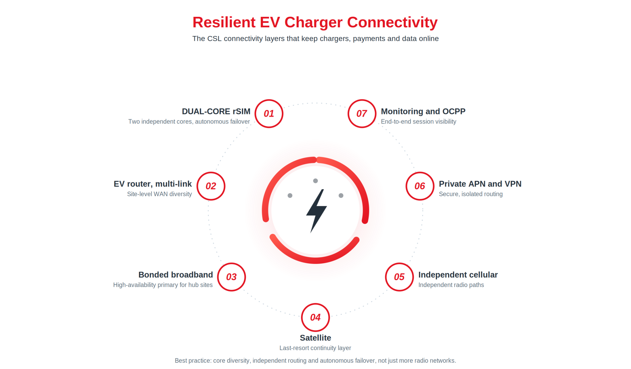
Figure 1. Resilient EV charger connectivity, the CSL way. The connectivity layers that keep EV chargers online: Dual-Core rSIM for autonomous failover across two cores, EV routers and multi-link site connectivity, bonded broadband, independent cellular and satellite paths, private APN and VPN routing, and monitoring with OCPP for session-success visibility.
FAQ paper
What is EV connectivity?
EV connectivity is the secure data connection between electric vehicles, EV chargers, charging platforms, payment systems, fleet systems and grid infrastructure.
For EV charging infrastructure, connectivity supports charger-to-back-office communication, payment authorisation, driver app workflows, roaming, remote diagnostics, load management, firmware updates and charger availability reporting. A charger that cannot communicate reliably can create a poor driver experience even when the electrical hardware itself is functioning.
- Charger-to-back-office communication through OCPP.
- Payment authorisation and settlement.
- Driver app, RFID, roaming and Plug & Charge workflows.
- Charger status updates and availability reporting.
- Remote diagnostics, rebooting and firmware updates.
- Load management and demand response.
- Fleet depot scheduling and energy optimisation.
- Security monitoring and certificate management.
What is EV charger connectivity?
EV charger connectivity is the communications service that links an EV charge point or EVSE to the systems needed to authorise, manage, monitor and optimise charging sessions.
For public charging, connectivity is especially important because the charger must often support real-time payment, open data, live availability reporting and remote support. For fleet charging, connectivity is critical because vehicles must be ready for operational departure windows. A failed overnight charging schedule can create a logistics failure, not just a lost charging transaction.
- A Charge Station Management System, or CSMS.
- Payment gateways and acquiring systems.
- Roaming platforms and eMobility Service Providers.
- Operator monitoring dashboards.
- Maintenance and support platforms.
- Grid, DSO or energy management systems.
- Fleet management platforms, where chargers serve commercial vehicles.
What is an EV router?
Site connectivity hardware. An EV router is an industrial or managed communications router used to connect one or more EV chargers to the internet, private network services or operator platforms.
An EV router is normally used where a site needs more capability than a single embedded SIM in a charger. It may support multiple chargers, higher bandwidth, external antennas, Ethernet, Wi-Fi, cellular failover, VPN tunnelling, private APN routing and remote device management.
A well-designed EV router does more than provide internet access. It acts as a managed resilience layer between the charging infrastructure and the services that keep chargers operational.
- Rapid and ultra-rapid charging hubs.
- Fleet depots.
- Retail forecourt charging sites.
- Highway charging locations.
- Car parks with multiple charge points.
- Sites where fixed broadband needs cellular backup.
- Remote locations requiring cellular or satellite fallback.
What is an EV charger router?
OCPP, payment and remote-diagnostics configuration. An EV charger router is a site router configured specifically for charge point connectivity, OCPP traffic, payment resilience, remote diagnostics and energy management data.
The phrase EV charger router is often used by installers, charge point operators and site hosts looking for a router that can connect one or more chargers reliably. The important distinction is that a charger router should be selected for operational resilience, not just signal strength.
- Multiple WAN options, such as broadband plus cellular.
- Multi-network cellular access.
- Dual SIM or resilient SIM options.
- Private APN support.
- Encrypted VPN connectivity.
- Remote monitoring and configuration.
- External antenna support.
- Automatic failover.
- Secure separation of charger traffic from public internet exposure.
What is an EV SIM card?
Cellular identity and data service. An EV SIM card is a cellular IoT SIM used to connect EV chargers, EV routers, fleet systems or vehicle telematics devices to mobile networks.
In charging infrastructure, EV SIM cards are often embedded directly into chargers, payment terminals, routers or site gateways. They allow devices to send and receive operational data over cellular networks where fixed-line connectivity is unavailable, expensive, delayed or unsuitable as a single point of dependency.
For EV charging, the quality of the SIM architecture matters. A SIM that can access multiple radio networks is useful, but it may not protect the charger from all failure modes if every network path still depends on the same underlying mobile core.
- 4G or 5G cellular connectivity.
- Multi-network roaming.
- Static IP addressing.
- Private APN connectivity.
- VPN routing.
- Data pooling across estates.
- Remote SIM provisioning.
- Device lifecycle management.
- Resilient failover between profiles or networks.
What is an EV charger SIM card?
Charger-embedded SIM deployment. An EV charger SIM card is a SIM provisioned specifically for charge point connectivity, remote charger management, payment workflows and charging network uptime.
The terms EV SIM card and EV charger SIM card are closely related, but the charger-specific phrase usually refers to a SIM used directly inside charging hardware or inside a charger router.
For public and fleet charging, the answer should not simply be whether the SIM has coverage. The better question is whether the SIM architecture reduces the probability and impact of failed charging sessions.
- Can the charger maintain OCPP connectivity?
- Can payment messages be routed securely?
- Can the operator remotely reboot or diagnose the charger?
- Does the SIM support private APN and VPN routing?
- Does it support roaming across more than one radio network?
- Does it protect against mobile core outages, or only local signal problems?
- Can the SIM communications plan be updated or reprovisioned remotely over the charger lifecycle?
- What happens if the management platform cannot reach the device?
Connectivity options at a glance
The table below summarises the main connectivity options for EV charging and where each is the better fit.
| Option | What it is | Resilience level | Best suited to |
| Standard IoT SIM | Single operator profile and one network path. | Basic. Coverage only. | Low-risk single chargers with robust built-in cellular hardware. |
| Multi-network SIM | Access to more than one radio access network. | Better coverage, but may still share one mobile core. | Sites where local signal or a single network gap is the main risk. |
| Resilient SIM (CSL rSIM) | Multiple operator profiles with autonomous, SIM-resident failover. | Core and operational resilience, independent of a reachable platform. | Critical chargers needing failover that does not depend on the management platform. |
| EV router | Site connectivity hardware for one or more chargers. | Site-level resilience, with multiple WAN options and failover. | Multi-charger sites, higher bandwidth, external antennas. |
| EV charger router | A router configured for OCPP traffic, payments and remote diagnostics. | Operational resilience tuned to charging traffic. | Hubs and forecourts needing managed, monitored connectivity. |
| Multi-link hub (CSL PACE) | Layered primary, alternate, contingency and emergency bearers. | Highest. Addresses correlated as well as local failures. | Ultra-rapid hubs, fleet depots and other high-value or SLA-bound sites. |
Are multi-network SIM cards enough for EV chargers?
A multi-network SIM can improve coverage, but it is not always enough to protect EV chargers from correlated or core-network outages.
Many multi-network SIMs allow a charger or router to connect to more than one radio access network. This helps when the issue is local signal quality or a single radio network coverage gap. However, some multi-network services still route traffic through a single shared mobile core. If that core fails, all the available radio networks may become irrelevant because the traffic still depends on the same central infrastructure.
For critical EV charging, operators should distinguish between multi-RAN resilience, core resilience, path resilience and operational resilience. The strongest architectures combine these layers rather than relying on coverage diversity alone.
- Multi-RAN resilience: the ability to use more than one radio access network.
- Core resilience: the ability to route through independent mobile core infrastructure.
- Path resilience: the ability to use different technologies, such as cellular, broadband and satellite.
- Operational resilience: the ability to detect faults, fail over, reconnect and recover without manual intervention.
What is Dual-Core connectivity for EV charging?
Dual-Core connectivity uses two independent mobile core paths so that an EV charger, router or SIM is not dependent on a single mobile core infrastructure.
This matters because many EV charging connectivity failures are not simple no-signal problems. A charger may have radio coverage but still fail to communicate if the underlying core, routing, authentication or platform path is unavailable.
Dual-Core connectivity is designed to reduce that single point of failure. In a Dual-Core architecture, the charger or router can use one profile or path as the primary connection and another independent profile or path as a backup. If the first path degrades or fails, traffic can move to the alternate path.
CSL provides this as DualCore, an architecture built on two genuinely independent mobile cores rather than several radio networks that share one core. This is the practical difference between true core diversity and a multi-RAN, single-core service, where every available radio network still depends on the same central infrastructure.
- Better protection against estate-wide cellular failures.
- More resilient OCPP communication.
- Greater payment path continuity.
- Faster recovery from connectivity degradation.
- Reduced need for manual SIM replacement or site attendance.
- Better support for regulated or SLA-driven charging services.
How does a resilient SIM differ from a standard IoT SIM?
A resilient SIM is designed to preserve service continuity, not just provide mobile data.
A standard IoT SIM may offer cellular access, data pooling and roaming. A resilient SIM should go further by supporting automated failover, remote provisioning and stronger independence between network paths.
For EV charging, this distinction matters because chargers are long-life infrastructure assets. A SIM may need to remain operational through changes in network coverage, technology generations, tariffs, platforms and regulatory expectations.
CSL’s rSIM is the eminent example of this approach. Its failover logic is resident on the SIM itself, so a charger can move to an alternative operator profile on its own, without waiting for an instruction from a management platform that may itself be unreachable during an outage. This is different from remote SIM provisioning under standards such as SGP.32 and the eIM, which manage the over-the-air download and activation of operator profiles. Provisioning governs which profiles a SIM can hold; rSIM’s autonomous failover governs how quickly the SIM moves between them when a path fails.
- Multiple operator profiles rather than a single static profile.
- SIM-resident or device-resident switching logic.
- Autonomous failover rather than purely platform-commanded switching.
- Private APN and VPN routing.
- Lifecycle management for long-term charger deployments.
- Reduced dependence on one mobile core or one management path.
When should a charger use an EV SIM card instead of an EV router?
A single embedded EV SIM card is often suitable for an individual charger, while an EV router is usually better for multi-charger sites, higher-bandwidth sites or locations requiring stronger resilience.
The right choice depends on site criticality, traffic levels, revenue exposure, regulatory obligations, physical location, signal conditions and the operational cost of downtime.
- A charger SIM may be suitable for a single AC charger, a small workplace charger installation, a destination charger with moderate usage, or a charger that already contains robust cellular hardware.
- An EV router is usually more suitable for rapid or ultra-rapid charging hubs, multi-bay charging sites, fleet depots, retail or highway charging locations, sites needing external antennas, and sites using broadband with cellular failover.
What connectivity does an AC charger need?
AC chargers usually need reliable but moderate-bandwidth connectivity for authorisation, billing, monitoring, reporting and load management.
AC charging is common in homes, workplaces, residential streets, hotels, car parks and destination locations. These sites may not always need the same resilience level as an ultra-rapid hub, but connectivity still matters.
For low-risk private installations, a simple cellular SIM or local network connection may be enough. For public AC charging or large workplace deployments, a managed SIM or router with failover can reduce support costs and improve user satisfaction.
- User authentication.
- Billing or reimbursement.
- Workplace or tenant allocation.
- Dynamic load management.
- Charger availability status.
- Fault alerts and remote reset.
- Firmware updates.
- Energy usage reporting.
What connectivity does a rapid or ultra-rapid charger need?
Rapid and ultra-rapid chargers need highly resilient connectivity because failed sessions have a larger commercial and customer impact.
A rapid charger is often used by drivers who need the charger to work immediately. A connectivity failure can prevent payment, authorisation, session start, remote support and status reporting. For motorway, retail, forecourt and public rapid charging locations, this creates a direct link between connectivity and revenue.
For the highest-value sites, operators should consider a multi-link architecture that layers several independent connectivity paths. CSL provides this layered approach as PACE, a multi-bearer stack in which everyday traffic runs over a primary bearer and fails over automatically through successive layers: a primary bonded broadband path that is always on, an alternate independent cellular path, a contingency alternative cellular path, and a satellite emergency layer for when all terrestrial links fail.
- Multi-network cellular coverage.
- Core-diverse SIM or router architecture.
- Private APN and VPN routing.
- Broadband plus cellular failover.
- External antennas.
- Router-level health checks.
- Remote reboot capability.
- Payment path monitoring.
- OCPP session monitoring.
- Functional uptime and session-success visibility.
What connectivity does a fleet charging depot need?
A fleet charging depot needs resilient connectivity because charging reliability affects vehicle availability, route fulfilment and service delivery.
Fleet depots often charge vehicles overnight or between shifts. If connectivity fails, the issue may not be visible until vehicles are not ready for service. Unlike public charging, the main cost may not be lost charging revenue; it may be missed deliveries, replacement vehicles, route disruption, SLA penalties or operational delays.
For commercial fleets, connectivity should be designed around operational continuity. The key question is not only whether the charger can connect, but whether the depot will still function if one connectivity path fails.
- Charger scheduling.
- Load balancing.
- Depot energy management.
- Vehicle readiness reporting.
- Fleet platform integration.
- Remote diagnostics and reset.
- Driver or vehicle authentication.
- Demand response and tariff optimisation.
- Backup connectivity for critical departure windows.
How does OCPP relate to EV connectivity?
OCPP is the communication protocol that allows EV chargers to exchange operational messages with a Charge Station Management System. EV connectivity is the network layer that carries those messages.
OCPP supports core charger operations such as authorisation, session control, meter values, status notifications, configuration changes and firmware updates. If the connectivity layer is unstable, OCPP messages may be delayed, lost or unavailable.
A charger may be physically capable of charging, but if OCPP communication fails, the operator may not be able to manage or monitor it effectively.
- Session start and stop.
- Charger availability status.
- Remote reset.
- Remote diagnostics.
- Firmware updates.
- Energy reporting.
- Fault alerts.
- Payment-related workflows.
- Compliance reporting.
Why do EV chargers need secure connectivity?
EV chargers need secure connectivity because they handle operational data, payment-related workflows, remote control functions and grid-facing services.
Security is not only about protecting data. It is also about preventing disruption to physical charging services. A weak connectivity architecture may expose chargers to unauthorised access, insecure routing, misconfiguration, certificate problems or avoidable service interruption.
As EV charging becomes more integrated with smart grids, fleets and payment systems, secure connectivity becomes a reliability requirement as well as a cybersecurity requirement.
- Private APN routing where appropriate.
- Encrypted VPN tunnels.
- Strong device identity.
- Secure remote management.
- Segmented traffic.
- Certificate lifecycle management.
- Logged access and configuration changes.
- Secure firmware update processes.
- Monitoring for unusual behaviour.
What is private APN connectivity for EV chargers?
A private APN provides a controlled mobile data path between EV charging devices and the operator systems, reducing reliance on the open public internet.
For EV chargers, a private APN can help route traffic more securely and predictably. It can also support static addressing, device management, VPN integration and better separation of charger traffic from general internet exposure.
A private APN does not, by itself, solve all resilience problems. It should be combined with good SIM, router, failover and monitoring architecture.
- Public charging networks.
- Fleet depots.
- Charge point operators.
- Critical infrastructure sites.
- Multi-site estates.
- Remote monitoring and diagnostics.
- Payment and OCPP traffic segmentation.
What is the difference between EV connectivity and EV telematics?
EV connectivity is the communications layer. EV telematics is the collection and use of vehicle or charger data to improve operations, safety, maintenance, routing, energy management or commercial performance.
In practice, they overlap. EV telematics depends on connectivity, and charging infrastructure depends on telematics-like data from chargers, vehicles and energy systems.
Without reliable connectivity, telematics data becomes incomplete, delayed or unavailable.
- EV connectivity enables data transmission, remote control, monitoring, payment and authorisation, security updates and platform integration.
- EV telematics uses data for fleet optimisation, battery and range monitoring, driver behaviour insights, predictive maintenance, charging schedule planning, energy cost optimisation, safety and compliance reporting.
What is the difference between independent and correlated connectivity outages?
An independent outage affects one charger, router or site. A correlated outage affects many chargers or sites at the same time because they share a common dependency.
Correlated outages are especially important for EV charging because they can take many chargers offline at once. A multi-network SIM may reduce local coverage problems but may not remove correlated risk if all traffic still depends on one shared core or platform path.
- Independent outages may include local signal loss, a failed modem, a damaged antenna, a charger configuration issue or a local router crash.
- Correlated outages may include mobile core failure, back-office platform failure, certificate or authentication failure, payment gateway incident, cloud region outage or shared routing/APN failure.
What should operators ask when buying EV connectivity?
Operators should ask practical, failure-based questions. The best EV connectivity solution is not necessarily the cheapest SIM or strongest local signal. It is the architecture that best protects the charging service.
- Does the solution support more than one radio network?
- Does it also support more than one independent mobile core?
- Does failover happen automatically?
- Does failover depend on a cloud platform that might itself be unreachable?
- Is traffic routed through a private APN or public internet path?
- Is VPN encryption included?
- Can the router, SIM or charger be monitored remotely?
- Can the charger be rebooted remotely?
- How are payment and OCPP traffic monitored?
- Does the solution report its own contribution to availability, and can that be correlated with your session-success data?
- Can the SIM be remotely provisioned or updated?
- What happens during a carrier outage?
- What happens if fixed broadband fails?
- Is satellite or another contingency path needed for the site?
- What is the operational cost of a failed charging session or failed depot departure?
Is offline mode a substitute for resilient EV connectivity?
No. Offline mode is a useful fallback, but it is not a substitute for resilient connectivity.
Offline mode can help avoid stranding drivers during short connectivity interruptions. For example, a charger may allow a known RFID card or trusted user to start a limited session while storing records for later reconciliation.
Offline mode should be treated as a bounded continuity feature. It reduces harm during short outages but does not remove the need for resilient connectivity.
- Payment authorisation.
- Roaming validation.
- Live charger status updates.
- Remote diagnostics.
- Firmware updates.
- Security certificate checks.
- Demand response.
- Real-time fleet scheduling.
- Dynamic pricing.
How should EV charging reliability be measured?
EV charging reliability should be measured by session success, not only by device uptime.
Device uptime may show whether a charger is powered on or reachable. Session success shows whether a driver can actually authenticate, pay and receive energy.
A charger can appear online but still fail from the user perspective. Measuring functional availability helps operators identify the gap between technical uptime and real customer experience.
- Session start success rate.
- Payment success rate.
- OCPP availability.
- Charger availability by connector.
- Mean time to detect faults.
- Mean time to repair faults.
- Remote fix rate.
- Failed authorisation rate.
- Failed payment rate.
- Failed charging session rate.
- Percentage of faults resolved without a site visit.
- Number of chargers affected by shared dependency failures.
Is it the charger, or the connection?
Many faults blamed on charger hardware are actually connectivity faults. If you recognise these patterns, the communications chain, not the unit, is the likely culprit:
- Chargers show “available” but drivers cannot start a session. The classic device-uptime gap: the CSMS thinks the charger is fine because it cannot see the failure the driver is hitting.
- Several chargers drop offline at the same time. Simultaneous loss across a site or estate points to a shared dependency (mobile core, platform, payment gateway or APN), not a local fault at each unit.
- Sessions fail at payment or authorisation, not at the connector. A routing or payment-path problem, where the energy hardware is ready but the transaction cannot complete.
- You cannot remotely reboot or diagnose a charger drivers say is not working. The management path has failed, which usually means an avoidable site visit.
- A carrier or network incident takes out chargers that share the same SIM profile. Coverage diversity did not help because every path still depended on one core.
- OCPP messages arrive late, out of order, or drop. Status and meter data lagging while the charger has power is a sign of an unstable or single-path connection.
- Field engineers find no fault on site, yet the fault recurs. “No fault found” visits are a strong indicator that the problem lives in the path, not the unit.
- Fleet vehicles are not ready at departure. Vehicles reach the shift short of charge because the overnight smart-charging schedule never reached the chargers, and nobody knew until departure. The energy hardware was fine; the scheduling and status path between the fleet platform and the chargers failed, and the cost is missed routes rather than lost revenue.
- Your reported uptime looks healthy but driver complaints and failed-payment rates do not match it. The gap between the headline number and real experience is the connectivity problem made visible.
Which EV connectivity architecture is best for each charger type?
For lower-risk charging, a managed cellular SIM may be enough. For high-revenue or operationally critical charging, a more resilient architecture is usually needed.
- Home and small private charging: usually suitable for local broadband, Wi-Fi or a simple cellular backup where billing or remote management requires it.
- Workplace charging: often benefits from managed connectivity for billing, access control, load management and reporting.
- Destination charging: needs reliable status, payment and user access. A managed SIM or router can reduce downtime and support calls.
- Public AC charging: should use secure managed connectivity with monitoring and remote diagnostics.
- Rapid public charging: should use resilient connectivity, preferably with failover, private routing and strong payment/OCPP monitoring.
- Ultra-rapid charging hubs: should use multi-link resilience, core diversity and remote operations because the revenue and user impact of downtime is higher.
- Fleet depots: should use resilient router-based connectivity with backup paths, remote diagnostics and integration into fleet and energy management systems.
- Remote or rural charging: may require cellular plus satellite or another contingency path where terrestrial coverage is limited.
Best connectivity approach by charger type
This table maps each charger type to its main connectivity priority and a recommended CSL approach, expressed in PACE layers.
| Charger type | Typical setting | Connectivity priority | Recommended approach |
| AC slow (3 to 7 kW) | Home, hotel, destination, residential. | Detection and remote management, since faults can persist undetected across an estate. | Managed SIM with monitoring, rSIM where uptime matters, offline mode as a fallback. |
| AC fast (7 to 22 kW) | Workplace, on-street, car park. | Coverage in marginal locations, plus remote reset. | Cellular with rSIM and DualCore, site Ethernet or Wi-Fi as a secondary path. |
| Public rapid (50 kW) | Forecourt, retail, mid-size hub. | Avoiding correlated outages across a shared gateway, plus SLA compliance. | DualCore cellular with rSIM, wired backhaul, payment and OCPP monitoring. |
| Ultra-rapid hub (150 to 350 kW) | Motorway services, major hub. | High revenue density, reputational exposure and correlated risk across many bays. | Full PACE stack: bonded broadband primary, independent cellular alternate, alternative cellular contingency, satellite emergency. |
| Fleet depot (22 to 150 kW) | Last-mile depot, bus garage, HGV yard. | Vehicle readiness and smart-charging continuity, with total correlated failure if connectivity is lost. | Wired primary to the energy management system, DualCore and rSIM, satellite, and a local fallback scheduler. |
| Rural or remote | Locations with limited terrestrial coverage. | Remote fix to avoid costly site visits, plus a contingency path. | rSIM multi-network with satellite contingency and remote diagnostics. |
Buyer checklist: EV SIM cards and EV routers for charging infrastructure
Before selecting an EV SIM card, EV charger SIM card, EV router or EV charger router, operators should confirm:
- The charger use case: AC, rapid, ultra-rapid, fleet depot, destination or remote.
- The commercial impact of failed sessions and the operational impact of remote maintenance loss.
- Signal strength and network availability at the site, including antenna options.
- Whether the solution is multi-RAN only or also core-diverse.
- Whether the backup path is truly independent of the primary path.
- Whether the site needs broadband, cellular, satellite or a layered combination.
- Whether private APN and VPN routing are included.
- Whether remote provisioning is supported over the expected charger asset life.
- Whether the router can be monitored and managed remotely.
- Whether the solution supports OCPP traffic requirements and payment-path monitoring.
- Whether the connectivity layer reports its own contribution to availability: link uptime per charger, failover events and their duration, reconnection time, and the number of chargers affected by shared-dependency outages.
- Whether that connectivity telemetry can be correlated with your CSMS and payment data, so session-success and failed-session reasons can be traced back to a connectivity cause where one exists.
- Whether failover is automatic and how it is triggered.
Conclusion
EV connectivity is now a fundamental part of charging infrastructure. EV routers and EV SIM cards are not simply accessories; they are the communications foundation for payments, OCPP, remote support, smart energy coordination, fleet scheduling and regulatory reporting.
For simple sites, a managed EV SIM card may provide sufficient connectivity. For public rapid chargers, ultra-rapid hubs and fleet depots, operators should consider more resilient architectures that combine multi-network access, core diversity, private routing, automatic failover, remote diagnostics and functional availability monitoring.
The key principle is simple: a charger is only as reliable as the full chain of systems required to start, manage and complete a charging session. EV connectivity should therefore be designed, procured and monitored as critical infrastructure.
Talk to CSL about resilient charging connectivity
CSL designs connectivity for EV charging as critical infrastructure. That means DualCore diversity, rSIM autonomous failover, private APN and VPN routing, the PACE multi-bearer stack and remote diagnostics, with monitoring that gives session-success visibility, by surfacing connectivity faults that would otherwise be misread as charger faults. To size the right architecture for your sites, and to model the cost of downtime across your estate, contact the CSL team.
Related resources
- Resilient Connectivity for EV Charging Infrastructure (CSL white paper): the full technical and economic case, including downtime cost by charger type. Read it on csl-group.com.
- Explore your ROI: share your estate profile and CSL will help you model the risk and build a resilience business case with you. Talk to the CSL team.
- rSIM solution overview: csl-group.com/solutions/rsim explains the autonomous SIM-resident failover described in this paper.
Glossary
- APN (Access Point Name). The gateway that connects a cellular device to a data network. A private APN routes charger traffic over a controlled path rather than the open public internet, supporting static addressing and tighter security.
- Correlated outage. A failure that takes many chargers or sites offline at once because they share a common dependency such as a mobile core, back-office platform or payment gateway. Contrast with an independent outage, which affects a single device or site.
- CSMS (Charge Station Management System). The back-office platform an operator uses to manage, monitor and control its chargers.
- Demand response. Adjusting charging load in response to grid signals or pricing to help balance demand on the network.
- Device uptime. A measure of whether a charger is powered on and reachable. It can overstate real availability, because a charger can be “up” yet still unable to complete a session.
- DSO (Distribution System Operator). The operator of the local electricity distribution network, increasingly responsible for managing demand-side flexibility on it. GB network operators have historically been known as DNOs.
- Dual-Core connectivity. An architecture built on two genuinely independent mobile cores, so traffic can move securely between them if one core fails, as distinct from several radio networks that share a single core. CSL’s implementation is DualCore.
- eMSP (eMobility Service Provider). A provider that gives drivers access to and payment across multiple charging networks, typically through an app or RFID, enabling roaming.
- eUICC. An embedded, reprogrammable SIM that can hold multiple operator profiles and be provisioned or switched remotely, rather than being tied to one network.
- eIM (eSIM IoT Remote Manager). In GSMA SGP.32, the network-side component that remotely manages eSIM profile operations (download, enable, disable, delete) across an IoT device or fleet, so profiles can be changed without relying on the device’s own interface.
- EVSE (Electric Vehicle Supply Equipment). The unit that supplies energy to one vehicle. A single physical charge point or device can contain more than one EVSE, so a dual-bay unit counts as two EVSEs.
- Failover. Automatic switching to a backup connection or path when the primary one degrades or fails.
- IoT SIM. A SIM designed for machine connectivity, usually supporting remote management, data pooling and long device lifecycles rather than consumer use.
- Mobile core. The central network infrastructure that authenticates, routes and manages traffic behind the radio network. Core diversity means using independent cores so a single core failure does not take everything down.
- OCPI (Open Charge Point Interface). An open protocol for sharing data and enabling roaming between charging networks and platforms. It is the platform-to-platform counterpart to OCPP, which connects a charger to its own back office.
- OCPP (Open Charge Point Protocol). The open protocol that carries operational messages between a charge point and a CSMS: authorisation, session start and stop, meter values, status, and firmware updates.
- Offline mode. A charger’s ability to start limited sessions for known users and store records for later reconciliation when connectivity is temporarily lost.
- PACE (CSL Multi-Link). A layered multi-bearer connectivity stack: a primary bonded broadband path, an independent cellular alternate, a second cellular contingency, and a satellite emergency layer.
- Plug & Charge. A capability defined in ISO 15118 where an EV and charger automatically authenticate the driver and authorise payment when the cable is connected, with no app or card needed.
- RAN (Radio Access Network). The part of a mobile network that connects devices to the core over radio. Multi-RAN means a device can use more than one operator’s radio network.
- RFID. A contactless card or fob used to authenticate a driver and start a charging session.
- Roaming. The ability to use chargers across multiple networks with a single account or payment method, enabled by interoperability and eMSPs.
- rSIM (CSL). A resilient SIM whose failover logic sits on the SIM itself, letting a device switch to an alternative operator profile autonomously, without waiting for an instruction from a management platform that may itself be unreachable.
- Session success (functional availability). Whether a driver can actually authenticate, pay and receive energy. A more meaningful measure of reliability than device uptime alone.
- Static IP. A fixed IP address assigned to a device, which aids secure remote access, management and routing.
- VPN. An encrypted tunnel that carries charger traffic securely across a shared or public network.