Orisec – CP Range – TTL
Panel Connection – TTL
|
Manufacturer |
Orisec |
|
Model |
CP Range |
|
Version |
CP-20 CP-25 CP-30 W-CP-40 CP-50 |
|
Minimum Panel Firmware |
CP-20 V1.00 CP-25 V1.10 CP-30 V3.10 W-CP-40 V1.42 CP-50 V1.84 CP-100 V1.84 CP-200 V1.84 |
|
Cable required? |
Provided with the DualCom Pro |
|
Panel Profile |
Orisec-CP-TTL |
|
Panel Connection |
TTL |
|
Technical Notes |
|
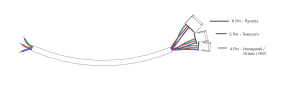
DualCom to Panel Wiring
The DualCom Pro can be powered from the AUX +12V and 0V terminals.
Use the 4 pin header of the cable provided and connect to the COM port on the panel.
On the DualCom Pro wire as below:
|
TTL-T |
Blue |
|
TTL-R |
Red |
|
RTN |
Green |
Panel Setup
Enter “Engineering Mode” using the appropriate Engineer Code.
From “Programming Menu”, navigate to “ARC-Setup Menu” 17.
Insert or Modify the following:
- Account = ARC Account ID
- Protocol = SIA3 or Contact ID
- Dial Seq = 2
- Reported = Set triggers as required
- Area = Set areas as required
- IP Address = Clear value
- IP Port = Clear value
Exit back to “Programming Menu”
Navigate to “Com Port Setup Menu” 13
Insert or Modify the following:
- Com Port = 1
- Mode = DualCom Pro
Exit “Engineering Mode”