RCO UC-50 – Dial Capture
Panel Connection – Dial Capture
|
Manufacturer |
RCO |
|
Model |
UC-50 with LS-50 interface |
|
Version |
N/A |
|
Minimum Panel Firmware |
N/A |
|
Cable required? |
MCM connected to: |
|
Panel Profile |
GENERIC-ALARMS-MCM-SE |
|
Panel Connection |
Dial Capture |
|
Technical Notes |
Attach the LS-50 interface card as described below by RCO. |
Panel Connection Information
|
DualCom Pro 1 – MCM plug-on module – Line A |
PSTN A |
|
DualCom Pro 1 – MCM plug-on module – Line B |
PSTN B |
Panel Programming
CONNECT THE ALARM TRANSMITTER TO LS-50
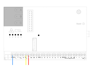
Connect incoming PSTN from the alarm transmitter to terminal P8 2 and 3 of the LS-50 interface that is mounted on UC-50

CONFIGURE ALARM TRANSMISSION IN R-CARD M5
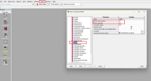
CONFIGURE LS-50
- Select Alarm > Alarm systems/alarm areas
- Select the Alarm areas tab
- Select the desired alarm system to display its settings

- Click the plus symbol ( ) by LS-50 alarm transmission interface
- Select PSTN enabled
- In the PSTN phone number prefix field, enter a comma (,)

- Click Save
CONFIGURE ALARM RECIPIENTS (CHANNELS)
- Click the plus symbol by Alarm recipients. Eight ”channels” are displayed

- Click the dialog opener for the ”channel” to be configured. The Alarm recipient dialog box opens
- Click New

- Enter a descriptive name
- In the Recipient type field, select SIA III protocol
- In the Phone number field, enter a fictional phone number such as 12345678.
- Click Save and then Close
- Now you must actively select the newly created alarm recipient. Do this by selecting it in the dropdown list

- Click Save in the main window.
- Click the plus symbol by your new “channel” to display its settings.
- For Number of connection attempts, use the dropdown box to select 1.

- Click Save
RCO power fail SIA code change
Open the M5 workstation:
Select ‘Alarm’ tab, then ‘Alarm characters’.
Select ‘Natfel’ and amend SIA-III codes to ‘YP and YQ’ and save:

The power fail codes signal in the expected way:

SELECT THE ALARM RECIPIENT (CHANNEL) IN THE ALARM AREA
- Select an alarm area
- Under Alarm transmission, select the alarm recipient(s)
- Click Save
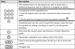
Diagnostics – LED SIGNALS IN LS-50
|
LED |
Description |
|
+5V |
The circuit board’s 5V voltage. |
|
TEL OUT |
Line status: – Steady light: Line relay active. The incoming line is disconnected from the outgoing PSTN line. (This is normally because LS-50 is using the line.) |
|
1 |
Status of telephone line (PSTN):
|
|
2 |
Not used. |
|
3 |
Alarm transmission:
|
|
4 |
Error. Normally off. Steady light means that an internal error has occurred. |
LS-50 Specifications
|
DC specification |
(t = +20°C) |
Min. |
Typ. |
Max. |
Unit |
|
Supply Voltage |
Powered from UC 50 |
– |
– |
– |
V |
|
Power Usage |
Idle Transmitting |
– |
15-19 27 |
– |
mA mA |
|
Temperature Range |
– |
+5 |
– |
+40 |
°C |
|
Weight: 27g |
– |
– |
– |
– |
– |