

Panel Connection – TTL
| Manufacturer | Texecom |
| Panel Series | Premier Elite Series |
| Models | 12, 24, 48, 88, 168, 640, 12-W, 24-W, 48-W, 64-W |
| Minimum Panel Firmware | v2.09.01 or v3 if using COM port 3 |
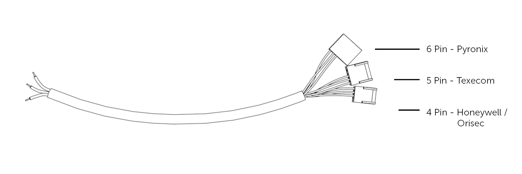
| Cable required? | 5 pin header on the cable provided with the DualCom Pro |
| Panel Profile | TEXECOM PREMIER TTL |
| Panel Connection | TTL |
| Technical Notes |
COM 1, COM 2 and COM 3 on the panel can all be used with the DualCom Pro. If the Texecom Premier Elite panel also has a SmartCom module then a ComPort Adapter may be required to provide a third com port for use with the DualCom Pro TTL connection. If this was not provided with the SmartCom module, these can be sourced from the distributors in packs of five (Part Code JAL-001). Line fault reporting is through the serial interface. No extra settings are required in either the panel or the DualCom Pro. Only SIA alarm format is supported. |
DualCom Pro to Panel Wiring
Connect the 5 pin header of the provided cable to the selected COM port on the panel and the wires to the DualCom Pro as detailed below.
| RTN | Green Wire |
| TTL-R | Blue Wire |
| TTL-T | Red Wire |
Different panel models have varying numbers of COM ports and in different positions on the board. Please refer to the manufacturer’s documentation to locate the appropriate COM port.
Panel Setup
- Enter the Engineer code (default 1234) to enter Engineering Programming Menu
- Select UDL/Digi Options (7 YES)
- Select Digi Options (4 YES)
- Ensure the first and last option are set to E****A
- Press Menu to go back to UDL/Digi Options
- If using upload/download, select UDL Options (5 YES)
- Leave all Callback numbers blank
- Select ‘UDL password’ and enter required password (1234 is the default)
- In ‘UDL Options’ ensure manual callback is enabled and call defeat is disabled (*M***)
- Leave ‘Rings Required’ as default (005)
- Leave ‘UDL Dial Attempts’ as default (003)
- Press Menu to go back to UDL/Digi Options
- Select ‘Area Accounts’
- A, B, C, D should be Blank (some panels will just have areas A & B as options)
- Select Program Digi (3 YES)
- If using SmartCom, it will use ‘ARC 1 Protocol’ so skip and select ‘ARC 2 Protocol’, if available
- Modify the selected ‘ARC Protocol’
- Set ‘ARC Protocol’ to ‘SIA level II’
- Set ‘Primary Number’ to be Blank
- Set ‘Secondary Number’ to be Blank
- Set ‘Account Number’ to the Connection ID number (see My Base) if required
- Set ‘Dialling Attempts’ to ‘02’
- Set ‘Reporting Areas’ as required by the installation
- Set ‘Reports’ as required (Final option should be set to ‘R’ to enable restores. If set to * you will see no restores)
- Set ‘Config 1’ as ******IT (I=Connect via IP and T=Send SIA Text)
- Set ‘Config 2’ (if available) to
- 1*** if using COM Port 1
- *2** if using COM Port 2
- **3* if using COM Port 3
- Press Menu to go back to UDL/Digi Options
- Select Setup Modules (7 YES)
- Select Setup IP Data (2 YES)
- Select the COM Port being used via the Yes key
- Select the COM Port being used via the Yes key
- Select Modem speed (9 YES) and make sure it is set to 19200
- Select the COM Port being used via the Yes key
- Press Menu to go back to UDL/Digi Options
- Select Setup IP Data (2 YES)
- Select Com Port Setup (8 YES)
- Select the COM Port being used to connect to the DualCom Pro (1, 2 or 3)
- Set this to Emizon/WebWayOne
- Press Menu to go back to UDL/Digi Options
- Select the COM Port being used to connect to the DualCom Pro (1, 2 or 3)
- Select Digi Options (4 YES)
- Log out of Engineer Mode
- Restart the Panel and the DualCom Pro to establish the electrical connection (this is mandatory)
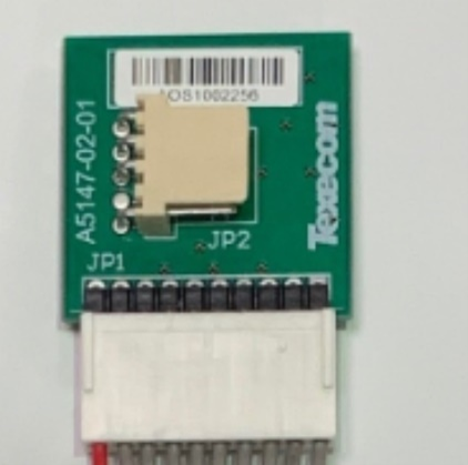
Installing The Plug-On Com Port Adapter
These can be ordered from distributors (Part Code JAL-001) and provide a 3rd COM port for when the first two are being used by Texecom’s SmartCom module.
Ensure the adapter is correctly installed with pin 1 matching on both the adapter and the control panel (this is normally signified by the red stripe on the ribbon cable).
Troubleshooting
- “ATS path fail com 1” refers to a communication path issue. This can be disabled via the following steps:
- Select Global Options > Monitor Hardware > Turn off P - ATS Path faults
- Select Area Programming > Options > ATS Path Faults - deselect all areas
- Select UDL/Digi Options > Com Port Set up > On board Digicom needs to be set to ‘nothing fitted'.
- Do not use any special characters within Area or Zone descriptions, this causes SIA alarm events to corrupt.
- Panels with firmware version 2.09 have COM Port Issues. Please upgrade to firmware 2.09.01 or later.
- Panels with firmware version 3.0x require COM Port 1 to be enabled in Protocol Options. Under ‘Program Digi' Menu > Config 2 > Set to use comm port 1.
- If only Com port 2 or 3 is available: Make sure the baud rate (modem speed) is set to 19200.
- If certain PA restores are not coming through, please ensure that within Area Programming, option 21 (Unarmed Tamper/ Fault Comms) is turned ON.