

Panel Connection – MCM
| Manufacturer | RCO |
| Model | UC-50 with LS-50 interface |
| Version | N/A |
| Minimum Panel Firmware | N/A |
| Cable required? |
MCM connected to |
| Panel Profile | GENERIC-ALARMS-MCM-SE |
| Panel Connection | Dial Capture |
| Technical Notes | Attach the LS-50 interface card as described below by RCO Download the R-CARD M5 software from RCO |
Panel Connection Information
| DualCom Pro 1 - MCM plug-on module - Line A DualCom Pro 2 - DI |
PSTN A | |
| DualCom Pro 1 - MCM plug-on module - Line B DualCom Pro 2 - AL |
PSTN B | |
Panel Programming
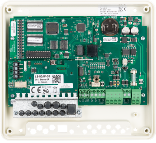
CONNECT THE ALARM TRANSMITTER TO LS-50
Connect incoming PSTN from the alarm transmitter to terminal P8 2 and 3 of the LS-50 interface that is mounted on UC-50
CONFIGURE ALARM TRANSMISSION IN R-CARD M5
CONFIGURE LS-50
1) Select Alarm > Alarm systems/alarm areas
2) Select the Alarm areas tab
3) Select the desired alarm system to display its settings
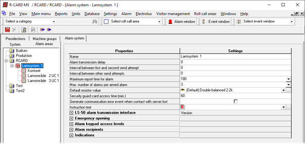
4) Click the plus symbol ( ) by LS-50 alarm transmission interface
5) Select PSTN enabled
6) In the PSTN phone number prefix field, enter a comma (,)
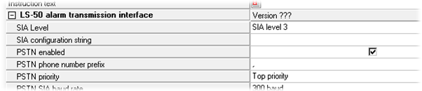
7) Click Save
CONFIGURE ALARM RECIPIENTS (CHANNELS)
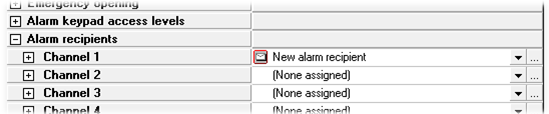
1) Click the plus symbol by Alarm recipients. Eight ”channels” are displayed
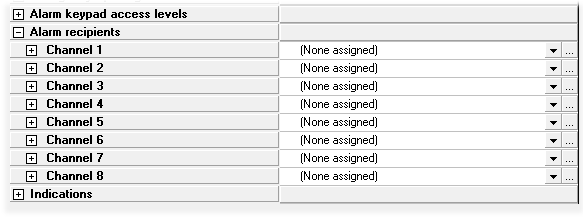
2) Click the dialog opener for the ”channel” to be configured. The Alarm recipient dialog box opens
3) Click New
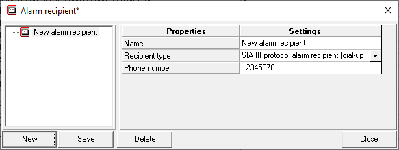
4) Enter a descriptive name
5) In the Recipient type field, select SIA III protocol
6) In the Phone number field, enter a fictional phone number such as 12345678.
7) Click Save and then Close
8) Now you must actively select the newly created alarm recipient. Do this by selecting it in the dropdown list:
9) Click Save in the main window.
10) Click the plus symbol by your new “channel” to display its settings.
11) For Number of connection attempts, use the dropdown box to select 1
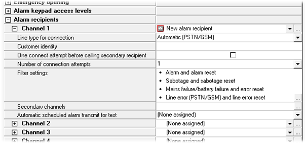
12) Click Save
SELECT THE ALARM RECIPIENT (CHANNEL) IN THE ALARM AREA
1) Select an alarm area
2) Under Alarm transmission, select the alarm recipient(s)
3) Click Save
Diagnostics
LED SIGNALS IN LS-50
| LED | Description |
| +5V | The circuit board's 5V voltage. Steady light: 5V voltage is OK. |
| TEL OUT |
Line status: - Steady light: Line relay active. The incoming line is disconnected from the outgoing PSTN line. (This is normally because LS-50 is using the line.) |
| 1 |
Status of telephone line (PSTN): - Steady light: Active. - Blinking: Active but no line is detected. |
| 2 | Not used. |
| 3 |
Alarm transmission: - Blinking: Alarm transmission in progress. |
| 4 | Error. Normally off. Steady light means that an internal error has occurred. |
LS-50 SPECIFICATIONS
| DC specification (t = +20°C) | Min. | Typ | Max. | Unit | |
| Supply Voltage | Powered from UC 50 | - | - | - | V |
| Transmitting | 27 | mA | |||
| Other | |||||
| Temperature Range | +5 | +40 | °C | ||
| Weight: 27g | . | ||||