Privacy Policy
Cookie Preferences
We use cookies and other tracking technologies to improve your browsing experience on our website, show you personalised content, and analyse our website traffic. Privacy Policy

This device should be mounted inside the Fire Alarm Panel or inside a separate powered housing using, the sticky mounting pads supplied. Enclosure requirements for the GradeShift UDL Fire are the same as for the Fire Alarm Panel itself. The enclosure must provide the facility to indicate the state of the fault and acknowledge outputs on the device. For Fire Alarm Panels, the enclosure must meet the requirements of EN54-21 7.3 (e.g. IP30 or above) and the supplied sticker should be applied to the outside of the housing.
The PSTN connection requires an analogue telephone line. Connecting other telecoms equipment in parallel to the analogue telephone line used by this device can stop the unit sending polling calls and alarm calls to an Alarm Receiving Centre. Parallel connection should never be used for this device when it is used in a Fire system application. The PSTN line should be supplied as ‘outgoing calls only’, i.e. incoming ringing barred. The PSTN line should also be ex-directory and connected to this device only. Other equipment can be connected to the A1 & B1 terminals (i.e. series connection) to make outgoing calls only. Modifications to the telephone or data provision (including changes to the local IT network when a LAN connection is used) might prevent or hinder the transmission of alarm information. Additionally, this could cause false alerts which might cause customer inconvenience and/or (where it is provided) result in withdrawal of emergency service response.
Note: GradeShift UDL Fire is sent out in EN54-21 Type 2 configuration (GPRS/PSTN). This is not configurable by the installer.
The interface to the Fire Control Equipment should be via inputs (pins) and relay outputs, as described below. The DualCom's ‘Dial Capture’ interface that emulates a PSTN line shall not be used, as it does not provide adequate status signalling back to the control equipment.
The alarm codes generated by these inputs are as follows:
| SIA | Contact ID | Fast Format |
| Pin 11: FA8011/FH8011 | Pin 11: Event 110 group 0 zone 11 | Pin 11 Channel 11 |
| Pin 12: FT8012/FJ8012 | Pin 12: Event 373 group 0 zone 12 | Pin 12 Channel 12 |
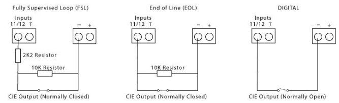
As default, inputs 11 and 12 are configured as digital inputs. They can be set up as End of Line (EOL) detection, Fully Supervised Loop (FSL) or digital inputs.
For FSL mode, a 10K and 2K2 end of line resistors should be fitted for detection of open circuit and short circuit. For EOL mode, a 10K end of line resistor should be fitted for detection of open circuit:
Inputs 11 and 12 can be configured for either EOL and FSL using the programmer menu:
A button 4 times to P
B button 3 times to Pi
A button 5 times to PF
B button 3 times to Fd
Use B button to scroll:
- Fd = DIGITAL
- FE = EOL
- FF = FSL
Press A button to select mode
Note: Pins 1 – 10 can be triggered but they will not send Fire Alarm/Fault signals.
For FSL or EOL, wire the negative supply (0V) to the panel relay common and the panel N/C terminal to the DualCom input pin with the 10K resistor in parallel.
For Digital, wire the negative supply to the panel relay common and the panel N/O terminal to the DualCom input.
To meet the EN54-21 requirements for monitoring on Type 1 and Type 2 Fire systems this device sends regular polling calls to the Gemini Network on all connected and active transmission paths. The Installer shall ensure that a reporting action has been agreed with the ARC for all alarm codes, transmission path failure notifications and Polling failure reports from the Gemini Platform.
Note: GradeShift UDL Fire has been designed to work as a Dual Path signalling device, installations that use only 1 signalling path will not meet the specified DP2 fault reporting times.
The Acknowledgment and Fault signals are triggered by the AUX Relay and Fault Relay respectively.
Depending on how the CIE input works (active high or active low), please wire them as follows:
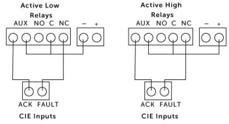
The fault relay labelled NC must be used. The device will ensure this remains open in a No Fault
condition and it will close when any of the following conditions are met:
Note: A Fire Alarm will not restore until all Faults (wiring or Panel) are cleared.
Note: Fault Relay should be wired to the Fire Panel fault input or to a separate light emitting indicator as required by EN54-21 5.3.b
The acknowledgement relay (ACK) is normally open. It closes when an acknowledgement of a Fire Alarm is received from the Gemini Platform. It is opened again when an acknowledgment of the Fire Alarm Restore signal is received from the Gemini Platform.
Note: The ACK relay will close even if an acknowledgment is received after the allotted time of 240 seconds (type 2) has expired, as in point 4 above.
The acknowledgement relay should be used to indicate the successful receipt of a Gemini Platform acknowledgement either at the Fire Alarm Panel or by a separate light emitting indicator, as required by EN54-21 5.3.a
 |
| 18 |
| DualCom GradeShift UDL CS5301-01 |
| CSL Group ????? Building 4, Croxley Park, Hatters Lane, Watford WD18 8YF United Kingdom |
| DoP No. 2544-CPR-P21310-F01-18 |
| EN 54-21:2006 Fire detection and fire alarm systems / Alarm transmission and fault warning routing equipment EN 50131-10:2014 EN 50136-1:2012 EN 50136-2:2013 |
| Notified Body No. 2544 |
| Type of transmission system: Type 1 (GPRS+IP) / Type 2 (GPRS+PSTN) Reporting time DP2 when installed as a Dual Path device. Environmental Class: II |