INSTALLATION
The CS0427 i-on Interface will plug onto any Cooper i-on Control Panel and enable direct connection to a CS53xx DualCom GradeShift UDL software version V3.14 (March 2014) or later, using the connection lead supplied. When connected and enabled, the DualCom will send any Fast Format, Contact ID or SIA alarm messages generated by the panel. In addition, it will enable up/downloading between the panel and i-on Programmer software via the DualCom and the Gemini® Managed Network (subject to installation of CSL UDL software and setup. Contact CSL Tech Support for more UDL information). When installing the i-on Interface, please note the following points in addition to instructions in the DualCom Installation Manual:
1) Before fitting the i-on Interface, locate the DualCom and apply power from the control panel to the ‘+’ & ‘-‘ terminals.
2) Using the DualCom’s A & B buttons, set the serial port to ‘i-on Panel’
- Press A until P appears on the display, then press B three times.
- Press A until P4 appears on display (‘4’ will flash), then press B 3 times.
- Press B to scroll through options until display shows ‘45’ (for the RS232 i-on)
- Press A to select this option.
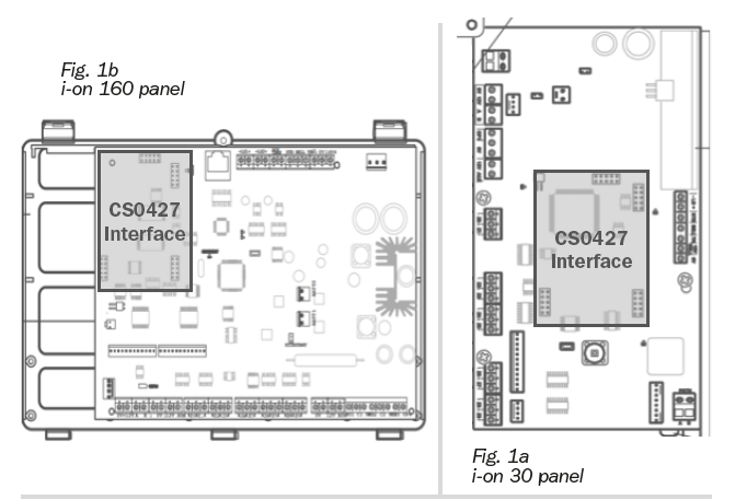
3) Once programmed, power down the control panel and DualCom then fit the i-on Interface onto the plug-on connectors on the control panel (see fig. 1a/1b) ensuring all pins are aligned correctly. Connect the supplied interface lead from the CS0427 interface to the DualCom RS232 port (see fig. 2).
NOTE: When the CS0427 i-on Interface is fitted to the control panel, an i-on digi modem or other communication device cannot be fitted to the same i-on connector.
4) Apply power to the control panel, also powering up the DualCom. After 30 seconds the red LEDs on the CS0427 Interface will start to flash – showing data is being exchanged.
5) Select the alarm reporting and up/download options on the i-on control panel as required (see Annex).
6) Your panel and DualCom are now ready to test in conjunction with your ARC. If you are also using Upload/Download we also recommended testing this before leaving site.

INTERFACE LED INDICATION
| LED Label | Description |
| Yellow | 232 LED Data being sent or received on the RS232 terminals |
| Green | PWR LED The Interface is powered from the control panel |
| Red | RX/TX LED Data being sent/received from the control panel |

“PPPP” = The account name as set in the Cooper downloader profile for this site/panel.
“QQQQ” = The panel serial number as set in the Cooper downloader profile for this site/panel.
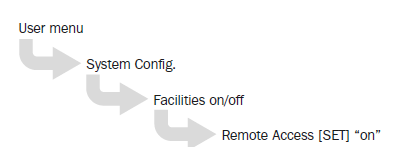
*Note: when selecting unattended remote access, the user menu below should also be set: