Privacy Policy
Cookie Preferences
We use cookies and other tracking technologies to improve your browsing experience on our website, show you personalised content, and analyse our website traffic. Privacy Policy

The DualCom Pro 4G Radio Module allows you to upgrade an existing/new DualCom Pro installation with an additional 4G signalling path. This Module can be remotely located inside the building using the supplied Radio Module Enclosure by connecting to the RS422 Data-Bus (max cable distance 50m). Locating the Radio Module away from the DualCom Pro enables the installation to benefit from better radio signal in other parts of the building and increases the security of your system.
When using an additional plug on board (i.e. 16 Pin input card or Module Capture Module) you must install the second Radio Module in the Radio Module Enclosure. Where not using an additional plug on board you can plug the Radio Module directly on to the DualCom Pro using the AUX port.
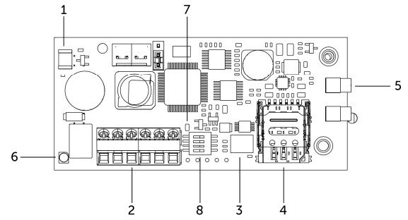
| 1 - Lid Tamper (Plastic-box mounted) | 5 - External Aerial Connectors |
| 2 - RS422 Data-Bus connections | 6 - Tri-Colour LED |
| 3 - MIM | 7 - Bi-Colour LED |
| 4 - SIM Carrier | 8 – DIP switches |
Tri-Colour - Large LED
| Colour | Mode | Meaning |
| Blue | Solid | No / Bad SIM |
| Red | Slow Flash | SIM not registered |
| Red | Solid | SIM Connected (Not commissioned to infrastructure) |
| Yellow | Solid | Connected, Commissioned - Communications LOST Comms |
| Green | Solid | Connected, Commissioned - Communications GOOD Comms |
| White | Fast Flash | Never seen a working path - BAD Comms |
Bi-Colour - Small LED
| Colour | Mode | Meaning |
| Red | Slow Flash | No usable signal |
| Red | Solid | Poor signal (Signal unreliable) |
| Amber | Solid | Normal signal |
| Green | Solid | Good signal |
| Red / Green | Alternating Blinking | Lost communication with the device |
| Red | Fast Flash | Power problems |
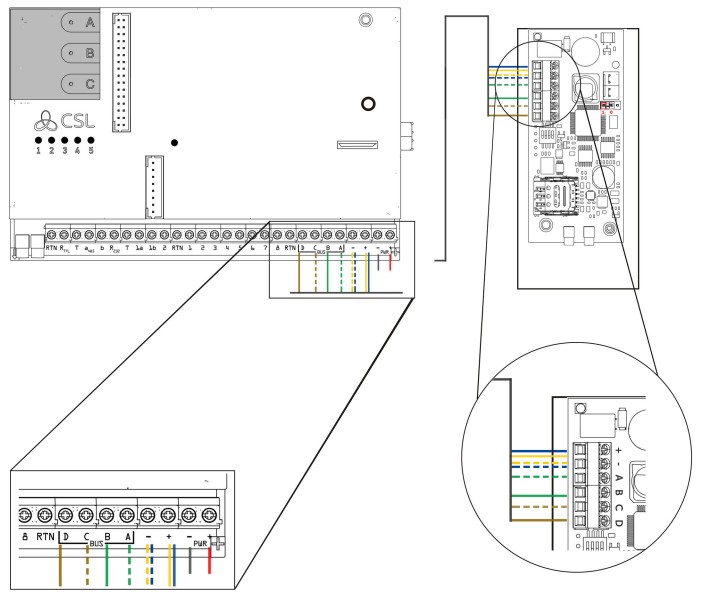
Using the 4G Radio/WiFi Module Enclosure
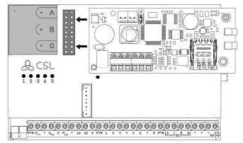
Connecting the DualCom Pro 4G Radio Module directly onto the device
The 4G Radio Module has a block of DIP-switches located under the Data-Bus Terminals. The table below describes their functionality.
| DIP Switch | Function | Configuration |
| DIP 1 | RS422/485 EOL | Switch to ON if running on remote RS422 Bus |
| DIP 2 | RS422 EOL | Switch to ON if running on remote RS422 Bus |
| DIP 3 | RS485 Mode | Always leave as OFF. |
| DIP 4 | Radio Module Signal Strength |
Switch to OFF to show radio module 1 signal strength Switch to ON to show radio module 2 signal strength |
Where the 4G Radio Module is taking its power from the DualCom Pro, a maximum cable run of 50 meters must not be exceeded. If additional cable length is required, a local power source is required to supply the 4G Radio Module with power.
| Technical Specifications | |
| Supply Voltage | 13.5v |
| Current Consumption | 35mA (average) 200 mA (max) |
| Dimension (PCB only) | (L) 85mm x (W) 35mm x (H) 20mm |
| Weight (Unpackaged) | 110g |
For more information on DualCom Pro and other products please contact CSL Technical Support:
UK Tel: +44 (0)1895 474 444
Ireland Tel: 1800 855 695
Email: support@csl-group.com
Hours: 08.30 to 18.00 weekdays, 10.00 to 16.00 Saturday