Privacy Policy
Cookie Preferences
We use cookies and other tracking technologies to improve your browsing experience on our website, show you personalised content, and analyse our website traffic. Privacy Policy

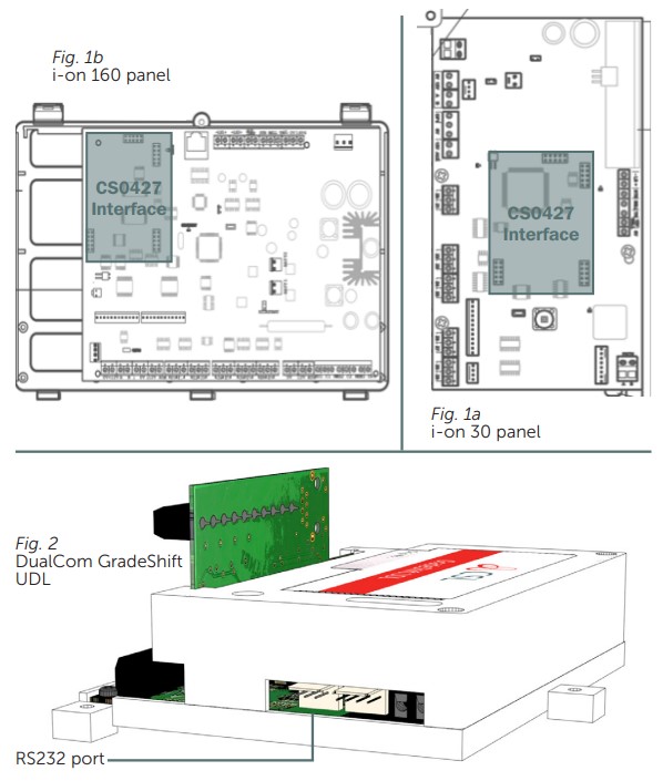
The Scantronic i-on Interface Board (CS0427) will plug onto any Scantronic i-on Control Panel and enable direct connection to a CS53xx DualCom GradeShift UDL software version V3.14 (March 2014) or later, using the connection lead supplied.
When connected and enabled, the DualCom will send any Fast Format, Contact ID or SIA alarm messages generated by the panel. In addition, it will enable up/downloading between the panel and i-on Programmer software via the DualCom and the Gemini Platform (subject to installation of CSL UDL software and setup. Contact CSL Technical Support for more UDL information).
When installing the i-on Interface Board, please note the following points in addition to instructions in the DualCom Installation Manual:
| When the i-on Interface Board is fitted to the control panel, an i-on digi modem or other communication device cannot be fitted to the same i-on connector. |
| LED Label | Description |
| Yellow 232 LED | Data being sent or received on the RS232 terminals |
| Green PWR LED | The Interface is powered from the control panel |
| Red RX/TX LED | Data being sent/received from the control panel |
To contact CSL Technical Support:
UK Tel: +44 (0)1895 474 444
Ireland Tel: 1800 855 695
Email: support@csl-group.com
Hours: 08.30 to 18.00 weekdays, 10.00 to 16.00 Saturday